12 | |
|
|
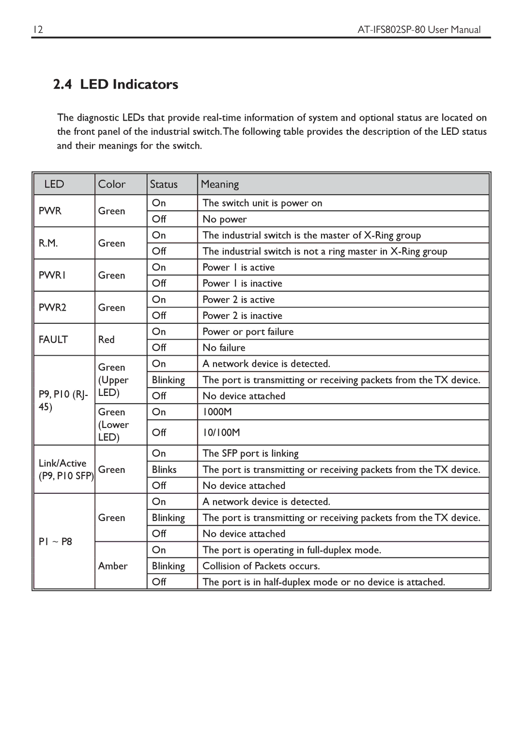
2.4 LED Indicators
The diagnostic LEDs that provide
|
|
|
|
|
|
| LED | Color | Status | Meaning |
|
|
|
|
|
|
|
| PWR | Green | On | The switch unit is power on |
|
|
|
|
| ||
| Off | No power |
| ||
|
|
|
| ||
|
|
|
|
|
|
| R.M. | Green | On | The industrial switch is the master of |
|
| Off | The industrial switch is not a ring master in |
| ||
|
|
|
| ||
|
|
|
|
|
|
| PWR1 | Green | On | Power 1 is active |
|
|
|
|
| ||
| Off | Power 1 is inactive |
| ||
|
|
|
| ||
| PWR2 | Green | On | Power 2 is active |
|
|
|
|
| ||
| Off | Power 2 is inactive |
| ||
|
|
|
| ||
| FAULT | Red | On | Power or port failure |
|
|
|
|
| ||
| Off | No failure |
| ||
|
|
|
| ||
|
|
|
|
|
|
|
| Green | On | A network device is detected. |
|
|
| (Upper | Blinking | The port is transmitting or receiving packets from the TX device. |
|
| P9, P10 (RJ- | LED) |
|
|
|
| Off | No device attached |
| ||
| 45) |
|
|
|
|
| Green | On | 1000M |
| |
|
|
| |||
|
| (Lower |
|
|
|
|
| Off | 10/100M |
| |
|
| LED) |
| ||
|
|
|
|
| |
|
|
|
|
|
|
| Link/Active |
| On | The SFP port is linking |
|
| Green | Blinks | The port is transmitting or receiving packets from the TX device. |
| |
| (P9, P10 SFP) |
| |||
|
| Off | No device attached |
| |
|
|
|
| ||
|
|
| On | A network device is detected. |
|
|
|
|
|
|
|
|
| Green | Blinking | The port is transmitting or receiving packets from the TX device. |
|
|
|
|
|
|
|
| P1 ~ P8 |
| Off | No device attached |
|
|
| On | The port is operating in |
| |
|
|
|
| ||
|
|
|
|
|
|
|
| Amber | Blinking | Collision of Packets occurs. |
|
|
|
|
|
|
|
|
|
| Off | The port is in |
|
|
|
|
|
|
|