Allied Telesis AT-IFS802SP manual Appendix A-RJ-45 Pin Assignment, RJ-45 Pin Assignments

Models: AT-IFS802SP

1 101
Download 101 pages 49.51 Kb
Page 77
Image 77

AT-IFS802SP-80 User Manual

73

Appendix 
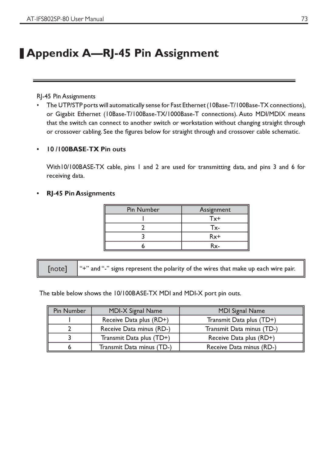
A—RJ-45 Pin Assignment

RJ-45 Pin Assignments

The UTP/STP ports will automatically sense for Fast Ethernet (10Base-T/100Base-TX connections), or Gigabit Ethernet (10Base-T/100Base-TX/1000Base-T connections). Auto MDI/MDIX means that the switch can connect to another switch or workstation without changing straight through or crossover cabling. See the figures below for straight through and crossover cable schematic.

10 /100BASE-TX Pin outs

With10/100BASE-TX cable, pins 1 and 2 are used for transmitting data, and pins 3 and 6 for receiving data.

RJ-45 Pin Assignments


Pin Number

Assignment


1

Tx+


2

Tx-


3

Rx+


6

Rx-


[note]

“+” and “-” signs represent the polarity of the wires that make up each wire pair.

The table below shows the 10/100BASE-TX MDI and MDI-X port pin outs.


Pin Number

MDI-X Signal Name

MDI Signal Name


1

Receive Data plus (RD+)

Transmit Data plus (TD+)


2

Receive Data minus (RD-)

Transmit Data minus (TD-)


3

Transmit Data plus (TD+)

Receive Data plus (RD+)


6

Transmit Data minus (TD-)

Receive Data minus (RD-)


Page 77
Image 77
Allied Telesis AT-IFS802SP manual Appendix A-RJ-45 Pin Assignment, RJ-45 Pin Assignments