PN 613-000813 Rev. B
AT-WR4500 Series
RouterOS v3 Configuration and User Guide
AT-WR4500 Series Ieee 802.11abgh Outdoor Wireless Routers
Limitation of Liability and Damages
Contents
IP Addresses and ARP
Routes, Equal Cost Multipath Routing, Policy Routing
121
117
118
120
166
Hot Spot Service 222
163
164
12.1.2 General Settings
10.3.7 Command Description
10.3.8 Service Port
Possible Error Messages
Figures
How This Guide is organized
Purpose of This Guide
Document Conventions
Tell Us What You Think
Sales or Corporate Information Management Software Updates
Allied Telesis FTP server ftp//ftp.alliedtelesis.com
Introduction
Admin@AT-WR4541g /system license print software-id NCL8-3TT
Features
Software License
Downloading WinBox loader
Accessing theWR4500 throughWinBox
Using WinBox
Logging in the AT-WR4500 Router
Password can be changed with the /password command
Accessing the CLI
AT-WR4500 Login admin Password
Aaaaaaaaaaa Ttttttt Aaaaaaa Aaaaa Tttt
Command Action
General Information
System Backup
Import Command
Export Command
General Information
Configuration Reset
Specifications
SoftwareVersion Management
Property Description
System Upgrade
To upgrade chosen packages
Step-by-Step
Adding Package Source
Submenu level /system upgrade upgrade-package-source
192.168.25.8 Admin
Software Package Management
Uninstallation
Installation Upgrade
Command name /system package uninstall
Name Version
Command name /system package downgrade
Admin@AT-WR4562 system package print Flags X disabled
Downgrading
Unscheduling
Suppose we need to test ipv6 package features
Command name /system package unschedule
Disabling and Enabling
Name Version Scheduled
Admin@AT-WR4562 system package unschedule security
Downloading 16 %
To upgrade selected packages
Software Package List
Download
Package name Contents Prerequisites Additional License
Package name Contents Prerequisites Additional License
Traffic Monitoring
General Interface Settings
Command name /interface monitor-traffic
Interface Status
Additional Resources
Ethernet Interface Configuration
Ethernet Interfaces
RelatedTopics
ARP
Command name /interface ethernet monitor
Monitoring the Interface Status
Type RX-RATE TX-RATE MTU
Troubleshooting
Wireless Interfaces
Default-cable-setting standard standard
Ack-timeout Range 5GHz 5GHz-turbo 2.4GHz-G
Quick Setup Guide
IP Addresses and ARP Log Management
35km 298
Wireless Interface Configuration
Submenu level /interface wireless
30km 249
AT-WR4500 Series Ieee 802.11abgh Outdoor Wireless Routers
Page
AT-WR4500 Series Ieee 802.11abgh Outdoor Wireless Routers
This example shows how configure a wireless client
Signal-to-noise 73dB tx-ccq 79% rx-ccq 46% p-throughput
Nstreme Settings
To see current interface settings
Submenu level /interface wireless nstreme
Submenu level /interface wireless nstreme-dual
Nstreme2 Group Settings
Example
Then add nstreme2 interface with exact-size framing
Submenu level /interface wireless registration-table
Admin@AT-WR4562 interface wireless nstreme-dual
RegistrationTable
No -38dBm.. Mbps
Admin@AT-WR4562 interface wireless registration-table
# Interface RADIO-NAME MAC-ADDRESS
Wlan1 000C42185C3D
Connect List
Access List
Submenu level /interface wireless connect-list
Submenu level /interface wireless access-list
Submenu level /interface wireless info
Info command
Page
AT-WR4500 Series Ieee 802.11abgh Outdoor Wireless Routers
Example
Virtual Access Point Interface
Submenu level /interface wireless wds
WDS Interface Configuration
Align
Submenu level /interface wireless align
Admin@AT-WR4562 interface wireless align
Command name /interface wireless align monitor
Align Monitor
Frequency Monitor
ManualTransmit PowerTable
Aproximately shows how loaded are the wireless channels
Submenu level /interface wireless manual-tx-power-table
Address Ssid Band Freq SIG RADIO-NAME AB R
Command name /interface wireless scan interfacename
Network Scan
Scan the 5GHz band
Security Profiles
Submenu level /interface wireless security-profiles
Page
Sniffer
Submenu level /interface wireless sniffer
Submenu level /interface wireless sniffer sniff
Wireless Sniffer Sniffs packets
Snooper
Submenu level /interface wireless snooper
Freq SIGNAL@RATE SRC DST Type
Sniffer Packets
Band Freq USE
Station and AccessPoint
Application Examples
Snoop 802.11b network
54Mbps
10.1.0.1/24 10.1.0.0 10.1.0.255 Admin@AccessPoint ip address
WDS Station
Configure the station and add an IP address 10.1.0.2 to it
Check whether you can ping the Access Point from Station
On WDS Access Point
Set wds-default-bridge to bridge1
Virtual Access Point
Test 4ghz-g
Virtual-test 4ghz-g
Nstreme network example
Nstreme
Monitor the link
Dual Nstreme
Ssid nstreme
Admin@DualNS-1 interface wireless nstreme-dual
Configure DualNS-1
Admin@DualNS-2 interface wireless nstreme-dual
Now complete the configuration for DualNS-1
WEP security example
WEP Security
Page
Admin@WEPStation1 interface wireless
Configure WEPStation1
WPA Security
Admin@WEPStationX interface wireless
Admin@WPAStation interface wireless
Test the link between Access point and the client
Admin@WPAAP interface wireless security-profiles
Admin@WPAStation interface wireless security-profiles
Vlan Interfaces
Vlan Setup
Vlan example on AT-WR4500 Routers
Application Example
Name MTU ARP
10.20.0.0 10.20.0.255 Pc1
10.10.10.0 10.10.10.255 Test Admin@AT-WR4562 ip address
Bridge Interfaces
10.0.0.0 10.0.0.255 Ether1
IP Addresses and ARP EoIP
Bridge Interface Setup
Interface bridge add name=MyBridge disabled=no
Add ether1 and ether2 to MyBridge interface
Submenu level /interface bridge port
Port Settings
Bridge Port Monitoring
Command name /interface bridge monitor
Command name /interface bridge port monitor
Bridge Monitoring
To monitor a bridge port
Command name /interface bridge host
Bridge Host Monitoring
Bridge Firewall General Description
Property Description
Page
Submenu level /interface bridge nat
Bridge Packet Filter
Bridge NAT
Submenu level /interface bridge filter
Submenu level /interface bridge broute
Bridge Brouting Facility
Troubleshooting
Submenu level /ip address
Configuring Interfaces Dhcp and DNS
IP Addresses and ARP
IP Addressing
2.1/24 2.0 2.255 Ether2
Address Resolution Protocol
10.10.10.0 10.10.10.255 Ether2 Admin@AT-WR4562 ip address
Submenu level /ip arp
Address MAC-ADDRESS
Proxy-ARP feature
Address MAC-ADDRESS Interface
Proxy ARP
Router setup is as follows
Consider the following configuration
Unnumbered Interfaces
RIP Routing Information Protocol
General Setup
Interfaces
Admin@AT-WR4562 routing rip
Submenu level /routing rip interface
Submenu level /routing rip network
Networks
Neighbors
Routes
10.0.0.174 10.0.0.255 Ether1
0.0.0 Ether1 Admin@AT-WR4562
To view the list of the routes
Ether1 1500 Ether2
Regular routing table is
Admin@AT-WR4562 routing rip set redistribute-connected=yes
10.0.0.0/24 Admin@AT-WR4562 routing rip network
0.0.0 Ether1 Admin@AT-WR4562 routing rip
Ospf
Alliedware+ Router Configuration
Routing table of the Alliedware+ router is
General Setup
Ospf Areas
Admin@AT-WR4562 routing ospf
Submenu level /routing ospf area
Network Area
Backbone 0.0 None Local10 10.5 Admin@WiFi routing ospf area
Submenu level /routing ospf network
Name AREA-ID
Submenu level /routing ospf interface
Virtual Links
Submenu level /routing ospf virtual-link
NEIGHBOR-ID
Virtual link should be configured on both routers
10.0.0.201 Admin@AT-WR4562 routing ospf virtual-link
Submenu level /routing ospf neighbor
Ospf Backup
Ospf backup without using a tunnel
Name Type RX-RATE Rate MTU
Authentication
Define new Ospf area named local10 with area-id
Add connected networks with area local10 in ospf network
Add the needed IP addresses
Name AREA-ID Stub DEFAULT-COST Authentication
Add the same area as in main router
Add connected networks with area local10
DST-ADDRESS Gateway Distance Interface
Admin@OSPFMAIN ip route print
Add connected networks with the same area
Connect, S static, r rip, o ospf, b bgp
Dead-interval=40s
Routing tables with Revised Link Cost
On OSPFpeer2
Functioning of the Backup
Routes, Equal Cost Multipath Routing, Policy Routing
NAT
Submenu level /ip route rule
Policy Rules
Static Equal Cost Multi-Path Routing example
Static Equal Cost Multi-Path routing
Standard Policy-Based Routing with Failover
Standard Policy-Based Routing with Failover
DST-ADDRESS Prefsrc Gateway
192.168.0.0 192.168.0.255 Local1
Packages required dhcp License required Level1
Dhcp Client and Server
Finally, add a Dhcp server
Check whether you have obtained a lease
Submenu level /ip dhcp-client
Dhcp Client Setup
To add a Dhcp client on ether1 interface
Dhcp Server Setup
Submenu level /ip dhcp-server
Property Description
Store Leases on Disk
Submenu level /ip dhcp-server config
Name Interface Relay
Submenu level /ip dhcp-server lease
Dhcp Networks
Dhcp Server Leases
Submenu level /ip dhcp-server network
Command Description
Submenu level /ip dhcp-server option
Dhcp Alert
Dhcp Option
Submenu level /ip dhcp-server alert
Name Code Value
Dhcp Relay
Use this option in Dhcp server network list
Submenu level /ip dhcp-relay
Questions
Command name /ip dhcp-server setup
Relay Ether1 10.0.0.1 Admin@AT-WR4562 ip dhcp-relay
Questions & Answers
# Address Gateway DNS-SERVER WINS-SERVER
Dynamic Addressing, using DHCP-Relay
IP addresses of DHCP-Server
Name Interface Relay ADDRESS-POOL LEASE-TIME ADD-ARP
DHCP-1
IP Address assignment, using FreeRADIUS Server
Configure respective networks
Create Dhcp Servers
Clients.conf file
Configure Radius Client on RouterOS
Setup Dhcp Server Create an address pool
Configure Dhcp networks
IP and Routing
DNS Client and Cache
Cache Monitoring
5Static DNS Entries
Static DNS Entries
Name Address
Command name /ip dns cache flush
6Flushing DNS cache
Flush clears internal DNS cache
Radius client
Radius Client Setup
Submenu level /radius incoming
Service CALLED-ID Domain Address
Ppp,hotspot 10.0.0.3 Admin@AT-WR4562 radius
ConnectionTerminating from Radius
Supported Radius Attributes
Suggested Radius Servers
XTRadius does not currently support MS-CHAP
Page
Page
Page
Name VendorID Value
Name VendorID Value RFC where it is defined
AT-WR4500 Series Ieee 802.11abgh Outdoor Wireless Routers
Submenu level /ppp profile
PPP User AAA
Local PPP User Profiles
L2TP Interface
Page
Submenu level /ppp secret
Local PPP User Database
Monitoring Active PPP Users
Command name /ppp active print
Name Service CALLER-ID Password Profile
Name Service CALLER-ID Address Uptime Encoding
Submenu level /ppp aaa
To enable Radius AAA
Router User AAA
PPP User Remote AAA
Submenu level /user group
Router User Groups
Exclamation sign ! just before policy item name means not
Only one, it cannot be removed
Admin@rb13 user group
Admin@AT-WR4562 user print Flags X disabled
Router Users
Router User Remote AAA
Command name /user active print
When Name Address
Monitoring Active Router Users
Generating key on a linux machine
To enable Radius AAA, enter the following command
SSH keys
Submenu level /user ssh-keys
Specific Properties
EoIP
IP Addresses and ARP Bridge Interfaces
EoIP Setup
Name User MTU CLIENT-ADDRESS Uptime ENC
Admin@OurGW interface pptp-server server set enable=yes
Admin@Remote interface pptp-client
EoIP Application Example
Interface Bridge Priority PATH-COST
Same for the Remote
Related Documents
Quick Setup Guide
Interface Bonding General Information
Summary
Property Description
10.1.0.0 10.1.0.255 Isp1
Application Examples
Isp1 Ether 1500 Isp2
1.1/24 1.0 1.255 Isp2
For Office2through ISP2
EoIP tunnel configuration For Office1 through ISP1
For Office2 through ISP1
For Office1through ISP2
For Office2
IPIPTunnel Interfaces
10.1.0.0 10.1.0.255 Isp1 3.1/24 3.0 3.255 Bonding1
Add an IP address to created ipip1 interface
Ipip Setup
Name MTU LOCAL-ADDRESS
Configuration of the R2 is shown below
Configuration on L2TP client router Add a L2TP client
Enable the L2TP server
L2TP Interface
IP Addresses and ARP AAA Configuration EoIP IP Security
2 L2TP Client Setup
Submenu level /interface l2tp-client
Monitoring L2TP Client
Command name /interface l2tp-client monitor
Example of an established connection
Submenu level /interface l2tp-server server
4 L2TP Server Setup
To enable L2TP server
5 L2TP Server Users
ENC
To add a static entry for ex1 user
Interface l2tp-server add user=ex1
Name User MTU CLIENT-ADDRESS Uptime
Router-to-Router Secure Tunnel Example
6 L2TP Application Examples
Then the user should be added in the L2TP server list
Add a L2TP client to the RemoteOffice router
Admin@HomeOffice interface l2tp-server server
Admin@HomeOffice ppp secret print detail Flags X disabled
Connecting a Remote Client via L2TPTunnel
Test the L2TP tunnel connection
Admin@RemoteOffice interface l2tp-server server
Server must be enabled
Admin@RemoteOffice ppp secret
FromLaptop Admin@RemoteOffice interface l2tp-server
ToInternet 1500
L2TP Setup for Windows
Admin@RemoteOffice interface ethernet
PPPoE
Now add a pppoe server
Add a user with username mike and password
Ip pool add name=pppoe-pool ranges=10.1.1.62-10.1.1.72
Submenu level /interface pppoe-client
PPPoE Client Setup
To monitor the pppoe-out1connection
PPPoE Server Setup Access Concentrator
Command name /interface pppoe-client monitor
Monitoring PPPoE Client
Admin@AT-WR4562 interface pppoe-server server
To view the currently connected users
PPPoE Users
PPPoE Server User Interfaces
Submenu level /interface pppoe-server
First of all, the wireless interface should be configured
PPPoE in a multipoint wireless 802.11g network
Admin@PPPoE-Server interface wireless
Finally, we can set up PPPoE clients
We should add PPPoE server to the wireless interface
Pptp
Admin@MT interface pppoe-server server
My Windows XP client cannot connect to the PPPoE server
Configuration on Pptp client router Add the Pptp client
Enable the Pptp server
IP Addresses and ARP PPP User AAA EoIP
Submenu level /interface pptp-client
Pptp Client Setup
Submenu level /interface pptp-server server
Pptp Server Setup
Command name /interface pptp-client monitor
Monitoring Pptp Client
Submenu level /interface pptp-server
To enable Pptp server
Pptp Users
PPTPTunnel Interfaces
Interface pptp-server add user=ex1
Pptp Application Examples
1460 10.0.0.202 6m32s None Pptp-in1 Ex1
Add a Pptp client to the RemoteOffice router
Admin@HomeOffice interface pptp-server add user=ex
Pptp-in1 Admin@HomeOffice interface pptp-server
Admin@RemoteOffice interface pptp-client
Test the Pptp tunnel connection
Connecting a Remote Client via Pptp Tunnel
FromLaptop Admin@RemoteOffice interface pptp-server
Connecting a Remote Client via and Encrypted Pptp Tunnel
IP Security
Pptp Setup for Windows
IP Addresses and ARP Firewall and QoS
Description
Diffie-Hellman Group Modulus Reference
Policy Settings
Submenu level /ip ipsec policy
Page
Submenu level /ip ipsec peer
Flags X disabled, D dynamic, I inactive
Peers
To view the policy statistics, do the following
Submenu level /ip ipsec remote-peers
Remote Peer Statistics
Local-addressread-only IP address local Isakmp SA address
Submenu level /ip ipsec installed-sa
Installed SAs
To see currently estabilished SAs
Command name /ip ipsec installed-sa flush
Flushing Installed SATable
Sample printout looks as follows
For Router1
To flush all the SAs installed
Tunnel mode example using AH with manual keying
RouterOS Router to RouterOS Router
Add accept and masquerading rules in SRC-NAT
IPsec Between two Masquerading RouterOS Routers
For Router2
Mangle Packet Flow
Filter
Firewall Filter
Submenu level /ip firewall filter
Page
Property Description
Page
Page
Block IP addreses called bogons
Filter Applications
Protect your RouterOS router
Protecting the Customers Network
Allow only needed icmp codes in icmp chain
Mangle
Create tcp chain and deny some tcp ports in it
Deny udp ports in udp chain
Submenu level /ip firewall mangle
Mangle
Filter Packet Flow
Page
Page
Page
Peer-to-PeerTraffic Marking
Admin@AT-WR4562 /ip firewall mangle add chain=forward \
Mark by MAC address
Mangle Filter
Packet Flow
Packet Flow
Change MSS
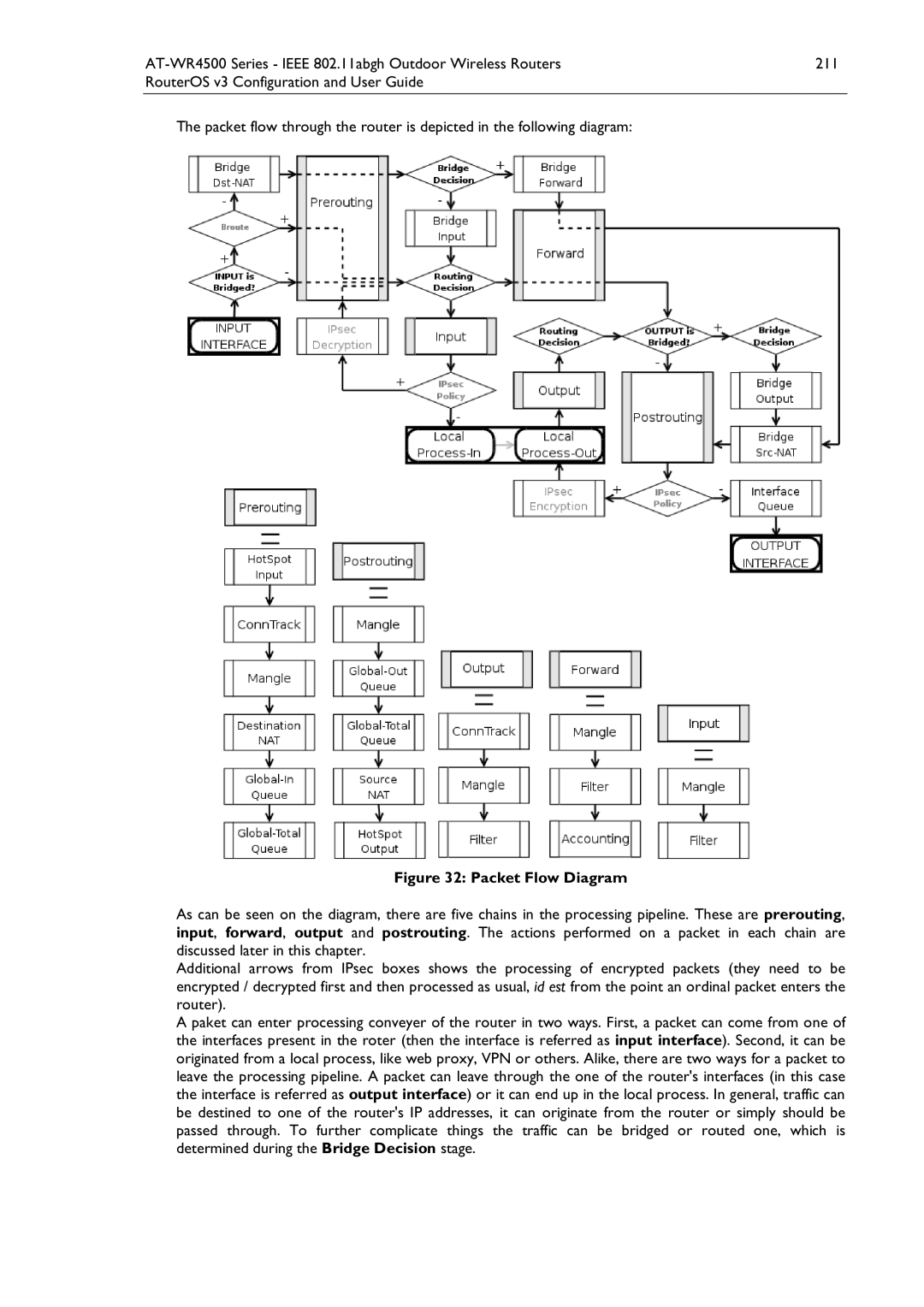
Packet Flow Diagram
Submenu level /ip firewall connection
ConnectionTracking
Submenu level /ip firewall connection tracking
ConnectionTimeouts
Submenu level /ip firewall service-port
Service Ports
General Firewall Information
Submenu level /ip firewall nat
NAT
2 NAT
Address-list parameter
Page
Page
Example of one to one mapping
NAT Applications
Example of Source NAT Masquerading
Example of Destination NAT
HotSpot Gateway
Hot Spot Service
HotSpot example network
Page
Page
Command name /ip hotspot setup
Question&Answer-Based Setup
Hs-local Local HS-real Default Admin@AT-WR4562 ip hotspot
HotSpot Interface Setup
Name Interface
Submenu level /ip hotspot profile
HotSpot Server Profiles
0s same as received
HotSpot Cookies
HotSpot User Profiles
HotSpot Users
Description
# User Domain MAC-ADDRESS
HTTP-levelWalled Garden
To get the list of valid cookies
Submenu level /ip hotspot walled-garden
Submenu level /ip hotspot ip-binding
IP-level Walled Garden
One-to-one NAT static address bindings
Submenu level /ip hotspot walled-garden ip
Service Port
Command Description
Active Host List
Chain=hotspot action=jump jump-target=pre-hotspot
Ftp Admin@AT-WR4562 ip hotspot service-port
Customizing HotSpot Firewall Section
To set the FTP protocol uses both 20 and 21 TCP port
Https proxy is listening on the 64875 port
Packets from the authorized clients through the hs-authchain
Chain=hs-input action=jump jump-target=pre-hs-input
Reject all packets to the clients with Icmp reject message
Serving Servlet Pages
Customizing HotSpot Http Servlet Pages
Href=$link-loginlogin/a
Page
Hey, your username is john $elif username == dizzy
Add the following line
To this line
Or alternatively add this line
To this
Before this one
Possible Error Messages
MAC-ADDRESS Address TO-ADDRESS Server
Name Interface ADDRESS-POOL Profile IDLE-TIMEOUT
HotSpot How-tos
Then we can use that certificate for hotspot
HotSpot User AAA
MAC-ADDRESS Address TO-ADDRESS Server IDLE-TIMEOUT
10.11.12.3 Hs-local
Page
Submenu level /ip hotspot user
Submenu level /ip hotspot active
HotSpot Active Users
Server Name Address Profile Uptime
To get the list of active users
10.0.0.144 4m17s 55m43s Admin@AT-WR4562 ip hotspot active
User Address Uptime
Vrrp Routers
Vrrp
Property Description
Submenu level /ip vrrp address
Flags X disabled, a active
Virtual IP addresses
Simple example of Vrrp fail over
Now this address should appear in /ip address list
Hardware Watchdog Management
SystemWatchdog
Submenu level /system watchdog
Admin@AT-WR4562 system watchdog
Admin@AT-WR4562 system watchdog set auto-send-supout=yes \
Automatic-supout yes Auto-send-supout yes
Topics
General Settings
Log Management
Submenu level /system logging
Submenu level /log
Actions
Log Messages
Submenu level /system logging action
Timemessage
Snmp Service
To view the local logs
To monitor the system log
Traffic Flow
General Configuration
Related Documents
Traffic-Flow Example
Admin@AT-WR4562 ip traffic-flow
Admin@AT-WR4562 ip traffic-flow target
Traffic-FlowTarget
Network Load Statistics Matrix
Host Information
Network load profile by time
General Options
Graphing
To store information on system drive every hour
Interface Graphing
Health Graphing
Simple Queue Graphing
ALLOW-ADDRESS
192.168.0.0/24 Yes Admin@AT-WR4562 tool graphing resource
Resource Graphing
Submenu level /tool graphing resource