OPERATION AND SERVICE PROCEDURES

(SLIDE IN MODELS)

TO AVOID THE RISK OF ELECTRIC SHOCK, PERSONAL INJURY OR DEATH DISCONNECT POWER BEFORE SERVICING, UNLESS TESTING REQUIRES IT.

set to read 120 VAC or higher, attach the meter leads to the L1 and N wire leads and turn on power to the range. A voltage reading of approximately 120 VAC should be indicated. If no voltage is indicated, check the range wiring. If 120 VAC is indicated shut off power to the range and reconnect L1 and N wire leads to the P.C. board terminals.

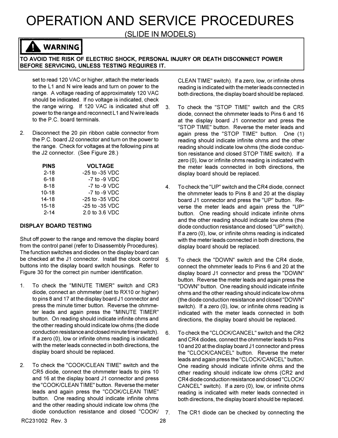
2.Disconnect the 20 pin ribbon cable connector from the P.C. board J2 connector and turn on the power to the range. Check for voltages at the following pins at the J2 connector. (See Figure 28.)

PINS

VOLTAGE

2-18

-25 to -35 VDC

6-18

-7 to -9 VDC

8-18

-7 to -9 VDC

10-18

-7 to -9

VDC

14-18

-25 to -35

VDC

15-18

-25 to -35

VDC

2-14

2.0 to 3.6

VDC

DISPLAY BOARD TESTING

Shut off power to the range and remove the display board from the control panel (refer to Disassembly Procedures). The function switches and diodes on the display board can be checked at the J1 connector. Install the clock control buttons into the display board switch housings. Refer to Figure 30 for the correct pin number identification.

1.To check the "MINUTE TIMER" switch and CR3 diode, connect an ohmmeter (set to RX10 or higher) to pins 8 and 17 at the display board J1 connector and press the minute timer button. Reverse the ohmme- ter leads and again press the "MINUTE TIMER" button. On reading should indicate infinite ohms and the other reading should indicate low ohms (the diode conduction resistance and closed minute timer switch). If a zero (0), low or infinite ohms reading is indicated with the meter leads connected in both directions, the display board should be replaced.

2.To check the "COOK/CLEAN TIME" switch and the CR5 diode, connect the ohmmeter leads to pins 10 and 16 at the display board J1 connector and press the "COOK/CLEAN TIME" button. Reverse the meter leads and again press the "COOK/CLEAN TIME" button. One reading should indicate infinite ohms and the other reading should indicate low ohms (the diode conduction resistance and closed "COOK/

RC231002 Rev. 3

CLEAN TIME" switch). If a zero, low, or infinite ohms reading is indicated with the meter leads connected in both directions, the display board should be replaced.

3.To check the "STOP TIME" switch and the CR5 diode, connect the ohmmeter leads to Pins 6 and 16 at the display board J1 connector and press the "STOP TIME" button. Reverse the meter leads and again press the "STOP TIME" button. One (1) reading should indicate infinite ohms and the other reading should indicate low ohms (the diode conduc- tion resistance and closed STOP TIME switch). If a zero (0), low or infinite ohms reading is indicated with the meter leads connected in both directions, the display board should be replaced.

4.To check the "UP" switch and the CR4 diode, connect the ohmmeter leads to Pins 8 and 20 at the display board J1 connector and press the "UP" button. Re- verse the meter leads and again press the "UP" button. One reading should indicate infinite ohms and the other reading should indicate low ohms (the diode conduction resistance and closed "UP" switch). If a zero (0), low, or infinite ohms reading is indicated with the meter leads connected in both directions, the display board should be replaced.

5.To check the "DOWN" switch and the CR4 diode, connect the ohmmeter leads to Pins 6 and 20 at the display board J1 connector and press the "DOWN" button. Reverse the meter leads and again press the "DOWN" button. One reading should indicate infinite ohms and the other reading should indicate low ohms (the diode conduction resistance and closed "DOWN" switch). If a zero (0), low, or infinite ohms reading is indicated with the meter leads connected in both directions, the display board should be replaced.

6.To check the "CLOCK/CANCEL" switch and the CR2 and CR4 diodes, connect the ohmmeter leads to Pins 10 and 20 at the display board J1 connector and press the "CLOCK/CANCEL" button. Reverse the meter leads and again press the "CLOCK/CANCEL" button. One reading should indicate infinite ohms and the other reading should indicate low ohms (CR2 and CR4 diode conduction resistance and closed "CLOCK/ CANCEL" switch). If a zero (0), low, or infinite ohms reading is indicated with meter leads connected in both directions, the display board should be replaced.

7.The CR1 diode can be checked by connecting the

28

Page 29
Image 29
Amana RST, RSS service manual Pins Voltage, Display Board Testing

RST, RSS specifications

The Amana RSS and RST series are designed to provide exceptional performance, efficiency, and reliability in various heating and cooling applications. These models stand out in the HVAC industry for their innovative features and technologies, making them ideal for both residential and commercial environments.

One of the main features of the Amana RSS and RST series is their advanced cooling and heating capabilities. They utilize a high-efficiency compressor that delivers powerful performance while minimizing energy consumption. This efficiency is bolstered by the inclusion of a variable-speed fan motor, which allows for precise control over airflow and temperature. As a result, these systems can operate in quieter modes, significantly reducing noise levels compared to traditional HVAC units.

The Amana RSS and RST models are equipped with a robust inverter technology that optimizes energy use by adjusting the compressor speed to match the thermal load. This constant modulation allows for better energy savings and improved indoor comfort. The systems also feature multi-stage cooling, which enhances temperature control and reduces humidity levels, ensuring a comfortable environment year-round.

In terms of technology, the Amana RSS and RST series incorporate smart controls that enable users to monitor and adjust their HVAC systems via smartphone apps or home automation systems. This connectivity provides users with real-time data on energy usage and system performance, allowing for more informed decisions about settings and schedules.

Durability is a significant characteristic of the Amana series, as they are built using high-quality materials that can withstand extreme weather conditions. Their components, including corrosion-resistant cabinets and durable coils, contribute to the longevity of the units, ensuring reliable operation for years to come.

Moreover, the Amana RSS and RST units come with a comprehensive warranty, reflecting the manufacturer's confidence in their products. Homeowners and businesses can benefit from this assurance, knowing their investment is protected.

Overall, the Amana RSS and RST series exemplify high efficiency, advanced technology, and robust construction, making them an excellent choice for those seeking dependable heating and cooling solutions. By prioritizing energy efficiency and user convenience, these models continue to set a standard in the HVAC industry.