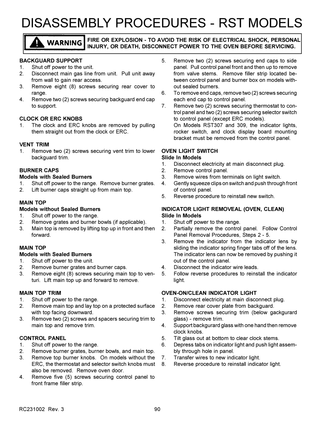
RST, RSS specifications
The Amana RSS and RST series are designed to provide exceptional performance, efficiency, and reliability in various heating and cooling applications. These models stand out in the HVAC industry for their innovative features and technologies, making them ideal for both residential and commercial environments.One of the main features of the Amana RSS and RST series is their advanced cooling and heating capabilities. They utilize a high-efficiency compressor that delivers powerful performance while minimizing energy consumption. This efficiency is bolstered by the inclusion of a variable-speed fan motor, which allows for precise control over airflow and temperature. As a result, these systems can operate in quieter modes, significantly reducing noise levels compared to traditional HVAC units.
The Amana RSS and RST models are equipped with a robust inverter technology that optimizes energy use by adjusting the compressor speed to match the thermal load. This constant modulation allows for better energy savings and improved indoor comfort. The systems also feature multi-stage cooling, which enhances temperature control and reduces humidity levels, ensuring a comfortable environment year-round.
In terms of technology, the Amana RSS and RST series incorporate smart controls that enable users to monitor and adjust their HVAC systems via smartphone apps or home automation systems. This connectivity provides users with real-time data on energy usage and system performance, allowing for more informed decisions about settings and schedules.
Durability is a significant characteristic of the Amana series, as they are built using high-quality materials that can withstand extreme weather conditions. Their components, including corrosion-resistant cabinets and durable coils, contribute to the longevity of the units, ensuring reliable operation for years to come.
Moreover, the Amana RSS and RST units come with a comprehensive warranty, reflecting the manufacturer's confidence in their products. Homeowners and businesses can benefit from this assurance, knowing their investment is protected.
Overall, the Amana RSS and RST series exemplify high efficiency, advanced technology, and robust construction, making them an excellent choice for those seeking dependable heating and cooling solutions. By prioritizing energy efficiency and user convenience, these models continue to set a standard in the HVAC industry.

