Chapter 1 - Physical Representation
Rear View of a Power Array
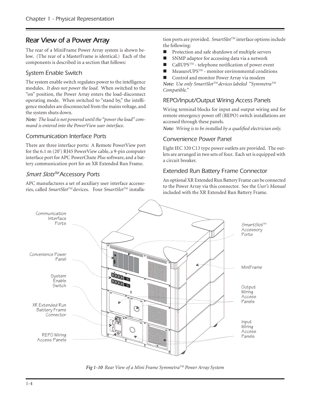
The rear of a MiniFrame Power Array system is shown be- low. (The rear of a MasterFrame is identical.) Each of the components is described in a section that follows:
System Enable Switch
The system enable switch regulates power to the intelligence modules. It does not power the load. When switched to the “on” position, the Power Array enters the
Note: The load is not powered until the “power the load” com- mand is entered into the PowerView user interface.
Communication Interface Ports
There are three interface ports: A Remote PowerView port for the 6.1 m (20') RJ45 PowerView cable, a
Smart SlotsTM Accessory Ports
APC manufactures a set of auxiliary user interface accesso- ries, called SmartSlotTM devices. Four SmartSlotTM installa-
Communication
Interface
Ports
Convenience Power
Panel
System
Enable
Switch
XR Extended Run
Battery Frame
Connector
REPO Wiring
Access Panels
tion ports are provided. SmartSlotTM interface options include the following:
nProtection and safe shutdown of multiple servers
nSNMP adaptor for accessing data via a network
nCallUPSTM - telephone notification of power event
nMeasureUPSTM - monitor environmental conditions
nControl and monitor Power Array via modem Note: Use only SmartSlotTM devices labeled “SymmetraTM Compatible.”
REPO/Input/Output Wiring Access Panels
Wiring terminal blocks for input and output wiring and for remote emergency power off (REPO) switch installations are accessed through these panels.
Note: Wiring is to be installed by a qualified electrician only.
Convenience Power Panel
Eight IEC 320 C13 type power outlets are provided. The out- lets are arranged in two sets of four. Each set is equipped with a circuit breaker.
Extended Run Battery Frame Connector
An optional XR Extended Run Battery Frame can be connected to the Power Array via this connector. See the User’s Manual included with the XR Extended Run Battery Frame.
SmartSlotTM
Accessory
Ports
MiniFrame
Output
Wiring
Access
Panels
Input
Wiring
Access
Panels
Fig