Chapter 4 - Electrical Requirements and Procedures
Input Wiring
nRead this chapter completely before installing wiring.
nVerify that all incoming line voltage (mains power) and low voltage (control) circuits are
nAlways verify that all battery modules are removed and all battery extension frames are disconnected from the Power Array before installing wiring.
Input Wiring Specifications
The Power Array requires a single phase 220V, 230V, or 240V
50or 60Hz incoming utility (mains) power source. A
All electrical service, both input and output, must be sized in accordance with local building codes. The circuit for input power must be adequate to carry the full load of the system and the load equipment. The
A 20 mm (3/4") knockout in the input wiring access panel provides access to the terminal blocks.
See table
Input Wiring Procedures
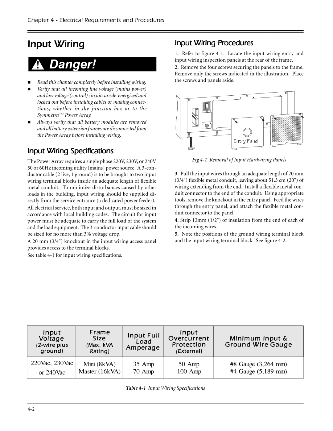
1.Refer to figure
2.Remove the four screws securing the panels to the frame. Remove only the screws indicated in the illustration. Place the screws and panels aside.
Entry Panel
Fig
3.Pull the input wires through an adequate length of 20 mm (3/4") flexible metal conduit, leaving about 51.3 cm (20") of wiring extending from the end. Install a flexible metal con- duit connector to the end of the conduit. Using appropriate tools, remove the knockout in the entry panel. Feed the wires through the entry panel, and attach the flexible metal con- duit connector to the panel.
4.Strip 13mm (1/2") of insulation from the end of each of the incoming wires.
5.Note the positions of the ground wiring terminal block and the input wiring terminal block. See figure
Input | Frame | Input Full | Input |
| |
Voltage | Size | Overcurrent | Minimum Input & | ||
Load | |||||
(Max. kVA | Protection | Ground Wire Gauge | |||
Amperage | |||||
ground) | Rating) | (External) |
| ||
|
| ||||
|
|
|
|
| |
220Vac, 230Vac | Mini (8kVA) | 35 Amp | 50 Amp | #8 Gauge (3,264 mm) | |
or 240Vac | Master (16kVA) | 70 Amp | 100 Amp | #4 Gauge (5,189 mm) | |
|
|
|
|
|
Table
