Chapter 7 - Configuring & Operating the SymmetraTM
screen has been reviewed, press the Enter key. The percent load with redundancy status screen appears.
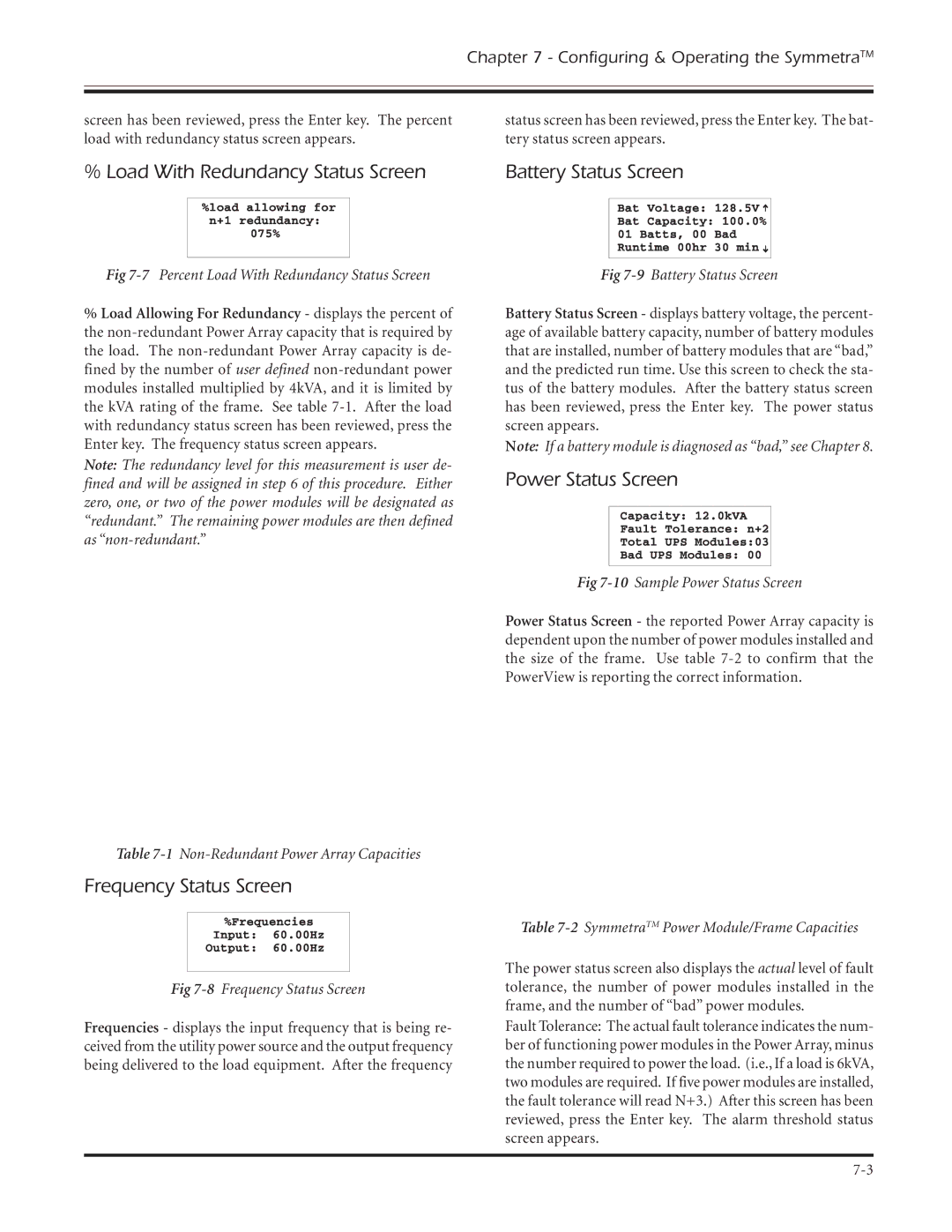
status screen has been reviewed, press the Enter key. The bat- tery status screen appears.
% Load With Redundancy Status Screen | Battery Status Screen | ||||
|
|
|
|
|
|
|
|
|
|
|
|
|
|
|
|
|
|
|
|
|
|
|
|
|
|
|
|
|
|
|
|
|
|
|
|
Fig 7-7 Percent Load With Redundancy Status Screen
%Load Allowing For Redundancy - displays the percent of the
Note: The redundancy level for this measurement is user de- fined and will be assigned in step 6 of this procedure. Either zero, one, or two of the power modules will be designated as “redundant.” The remaining power modules are then defined as
Table 7-1 Non-Redundant Power Array Capacities
Fig 7-9 Battery Status Screen
Battery Status Screen - displays battery voltage, the percent- age of available battery capacity, number of battery modules that are installed, number of battery modules that are “bad,” and the predicted run time. Use this screen to check the sta- tus of the battery modules. After the battery status screen has been reviewed, press the Enter key. The power status screen appears.
Note: If a battery module is diagnosed as “bad,” see Chapter 8.
Power Status Screen
Fig 7-10 Sample Power Status Screen
Power Status Screen - the reported Power Array capacity is dependent upon the number of power modules installed and the size of the frame. Use table
Frequency Status Screen
|
|
| Table |
|
|
| The power status screen also displays the actual level of fault |
|
|
| |
Fig | tolerance, the number of power modules installed in the | ||
|
|
| frame, and the number of “bad” power modules. |
Frequencies - displays the input frequency that is being re- | Fault Tolerance: The actual fault tolerance indicates the num- | ||
ceived from the utility power source and the output frequency | ber of functioning power modules in the Power Array, minus | ||
being delivered to the load equipment. After the frequency | the number required to power the load. (i.e., If a load is 6kVA, | ||
|
|
| two modules are required. If five power modules are installed, |
|
|
| the fault tolerance will read N+3.) After this screen has been |
|
|
| reviewed, press the Enter key. The alarm threshold status |
|
|
| screen appears. |
|
|
|
|
|
|
| |