Chapter 8 - Module Replacement
Power Module Replacement
1. Remove the appropriate grill cover. The power module bays are labeled on the center spine of the frame, behind the grill covers.
Note: If replacing a
2. Use a flathead screwdriver to release the flip latch from the power module. See figure
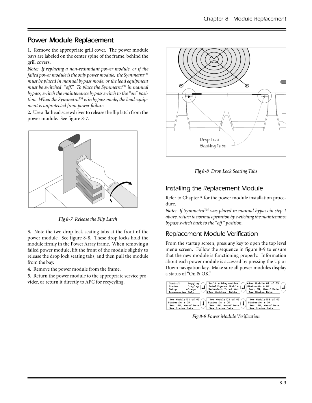
Drop Lock
![]()
![]()
![]()
![]()
![]()
![]() Seating Tabs
Seating Tabs
Fig
3.Note the two drop lock seating tabs at the front of the power module. See figure
4.Remove the power module from the frame.
5.Return the power module to the appropriate service pro- vider, or return it directly to APC for recycyling.
Fig
Installing the Replacement Module
Refer to Chapter 5 for the power module installation proce- dure.
Note: If SymmetraTM was placed in manual bypass in step 1 above, return to normal operation by switching the maintenance bypass switch back to the “off” position.
Replacement Module Verification
From the startup screen, press any key to open the top level menu screen. Follow the sequence in figure
Fig