Chapter 5 - System Setup
Installing the Power Modules
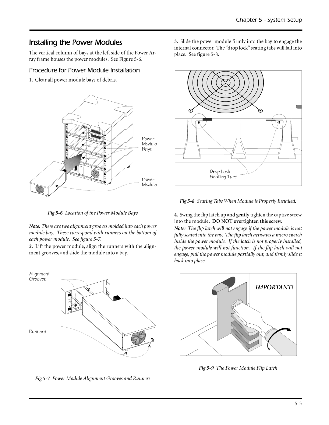
The vertical column of bays at the left side of the Power Ar- ray frame houses the power modules. See Figure
3.Slide the power module firmly into the bay to engage the internal connector. The “drop lock” seating tabs will fall into place. See figure
Procedure for Power Module Installation
1.Clear all power module bays of debris.
Power |
|
Module |
|
Bays |
|
| Drop Lock |
Power | Seating Tabs |
Module |
|
Fig
Note: There are two alignment grooves molded into each power module bay. These correspond with runners on the bottom of each power module. See figure
2.Lift the power module, align the runners with the align- ment grooves, and slide the module into a bay.
Alignment
Grooves
Runners
Fig
Fig
4.Swing the flip latch up and gently tighten the captive screw into the module. DO NOT overtighten this screw.
Note: The flip latch will not engage if the power module is not fully seated into the bay. The flip latch activates a micro switch inside the power module. If the latch is not properly installed, the power module will not function. If the flip latch will not engage, pull the power module partially out, and firmly slide it back into place.
IMPORTANT! |
Fig