Chapter 4 - Electrical Requirements and Procedures
Output Wiring
nRead this chapter completely before installing wiring.
nVerify that all incoming line voltage (mains power) and low voltage (control) circuits are
nAlways verify that all battery modules are removed and all battery extension frames are disconnected from the Power Array before installing wiring.
Output voltage is delivered to the load equipment via hardwired connections and/or via eight IEC 320 C13 power outlets at the rear of the Power Array. To facilitate mainte- nance and service of the Power Array, use flexible metal con- duit for all hardwiring connections.
See table
Output Wiring Installation
1.Refer to Fig
2.Pull the L1, Neutral, and Ground wires through conduit, leaving about 51.3 cm (20") of wiring extending from the end. Install a flexible metal conduit connector to the end of the conduit. Using appropriate tools, remove the knockout in the entry panel. Feed the wires through the entry panel, and attach the flexible metal conduit connector to the panel. Strip 13 mm (1/2") of insulation from the end of each of the incoming wires.
3.Connect output wiring to the output terminal connec- tions as shown in figure
L1 Wire Connection
Neutral Wire
Connection
Ground Wire
Connection
Fig. 4-7 Output Hardwiring Connections
4.Carefully fold the excess wiring into the entry compart- ment. After the electrical wiring test/checklist at the end of this chapter is completed, replace the input wiring panels.
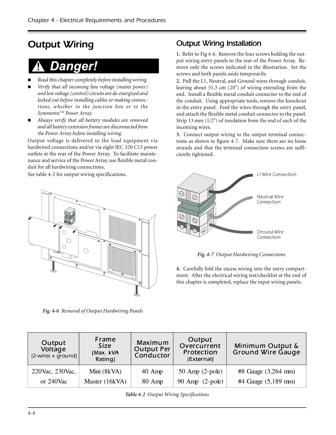
Fig. 4-6 Removal of Output Hardwiring Panels
Output | Frame | Maximum | Output |
| |
Size | Overcurrent | Minimum Output & | |||
Voltage | Output Per | ||||
(Max. kVA | Protection | Ground Wire Gauge | |||
Conductor | |||||
Rating) | (External) |
| |||
|
|
| |||
|
|
|
|
| |
220Vac, 230Vac, | Mini (8kVA) | 40 Amp | 50 Amp | #8 Gauge (3,264 mm) | |
or 240Vac | Master (16kVA) | 80 Amp | 90 Amp | #4 Gauge (5,189 mm) | |
|
|
|
|
|
Table