Chapter 6 - The PowerView Display
Setup
nSet the system shutdown parameters
nSet the alarm thresholds
nSet input/output voltage frequency synchronization range
nSet system to go to bypass mode, or not go to bypass mode, if voltage frequency synchronization is out of an acceptable range when a power module failure occurs
nSet “self test at power up” on or off
nSet system ID
nSet output voltage to 220V, 230V or 240V
nCopy system settings to another PowerView
Accessories
nMonitors SmartSlotTM Accessory cards (if present)
Logging
nView the last 64 power or user events
nSelect the events that are to be recorded in the event log
nClear event log
nView statistical representation of log data
nView logged events by group
Display
nConfigure the date and time
nSet a password
nDisplay the “about system” information
nSet audible alarm parameters and volumes
nSet screen contrast
nConfigure the startup screen
Diagnostics
nDisplay the reason a failure, change or alarm has occurred
nReview status of the main intelligence module (MIM)
nReview status of redundant intelligence module (RIM)
nReview status of the power modules
nReview status of the battery modules
Help
nThe help menu opens online help.
Note: Context sensitive help is available for most screens. Press the up and down navigation keys simultaneously to access context sensitive help.
French, Italian, German or Spanish Language Configuration
The factory default PowerView language is English. It can be configured to display French, Italian, German or Spanish text by replacing an EPROM (erasable, programmable read only memory) chip. A set of replacement EPROM chips are in- cluded with the PowerView. Follow these steps to replace the language EPROM:
Note: The internal circuitry of the PowerView, and the EPROM are sensitive to static electricity. Use all necessary precautions to eliminate static electricity from yourself and all tools before replacing the chip. Do not remove the chip from the protective case until you are ready to install it in the PowerView.
nBefore disassembling the PowerView, touch a grounded metal object to thoroughly ground all static charge.
nThe PowerView cable must be disconnected from the PowerView before proceeding.
1.Working on a flat table or other suitable work surface, re- move the four Phillips screws at the rear of the PowerView. Separate the back half from the PowerView.
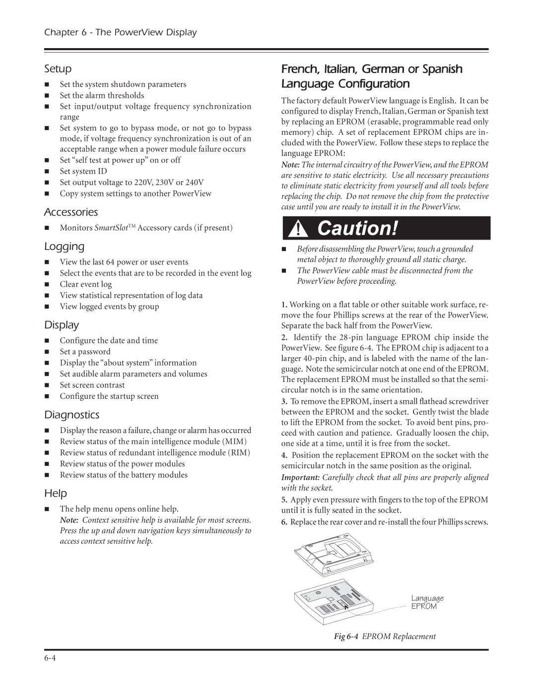
2.Identify the
3.To remove the EPROM, insert a small flathead screwdriver between the EPROM and the socket. Gently twist the blade to lift the EPROM from the socket. To avoid bent pins, pro- ceed with caution and patience. Gradually loosen the chip, one side at a time, until it is free from the socket.
4.Position the replacement EPROM on the socket with the semicircular notch in the same position as the original. Important: Carefully check that all pins are properly aligned with the socket.
5.Apply even pressure with fingers to the top of the EPROM until it is fully seated in the socket.
6.Replace the rear cover and
Language
EPROM
Fig