Chapter 6 - The PowerView Display
PowerView LED Indicators
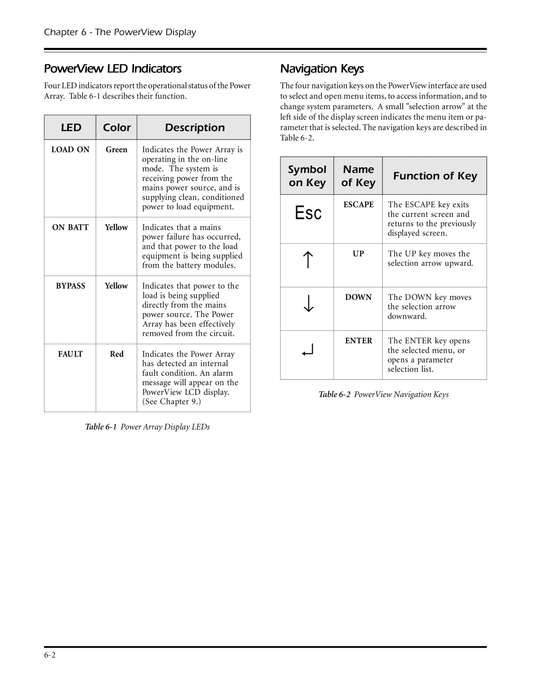
Four LED indicators report the operational status of the Power Array. Table
LED | Color | Description |
|
|
|
LOAD ON | Green | Indicates the Power Array is |
|
| operating in the |
|
| mode. The system is |
|
| receiving power from the |
|
| mains power source, and is |
|
| supplying clean, conditioned |
|
| power to load equipment. |
|
|
|
ON BATT | Yellow | Indicates that a mains |
|
| power failure has occurred, |
|
| and that power to the load |
|
| equipment is being supplied |
|
| from the battery modules. |
|
|
|
BYPASS | Yellow | Indicates that power to the |
|
| load is being supplied |
|
| directly from the mains |
|
| power source. The Power |
|
| Array has been effectively |
|
| removed from the circuit. |
|
|
|
FAULT | Red | Indicates the Power Array |
|
| has detected an internal |
|
| fault condition. An alarm |
|
| message will appear on the |
|
| PowerView LCD display. |
|
| (See Chapter 9.) |
|
|
|
Table
Navigation Keys
The four navigation keys on the PowerView interface are used to select and open menu items, to access information, and to change system parameters. A small "selection arrow" at the left side of the display screen indicates the menu item or pa- rameter that is selected. The navigation keys are described in Table
Symbol | Name | Function of Key | |
on Key | of Key | ||
| |||
|
|
| |
Esc | ESCAPE | The ESCAPE key exits | |
| the current screen and | ||
|
| returns to the previously | |
|
| displayed screen. | |
|
|
| |
− | UP | The UP key moves the | |
| selection arrow upward. | ||
|
|
| |
↓ | DOWN | The DOWN key moves | |
| the selection arrow | ||
|
| downward. | |
|
|
| |
↵ | ENTER | The ENTER key opens | |
| the selected menu, or | ||
|
| opens a parameter | |
|
| selection list. | |
|
|
|
Table
