Chapter 4 - Electrical Requirements and Procedures
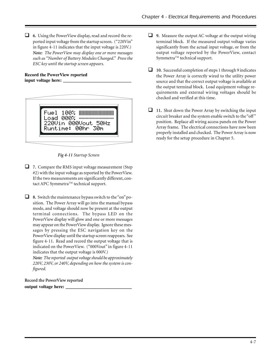
q6. Using the PowerView display, read and record the re- ported input voltage from the startup screen. (“220Vin” in figure
Record the PowerView reported
input voltage here: ______________________________
Fig 4-11 Startup Screen
q7. Compare the RMS input voltage measurement (Step #2) with the input voltage as reported by the PowerView. If the two measurements are significantly different, con- tact APC SymmetraTM technical support.
q8. Switch the maintenance bypass switch to the “on” po- sition. The Power Array will go into the manual bypass mode, and voltage should now be present at the output terminal connections. The bypass LED on the PowerView display will glow and one or more messages may appear on the PowerView display. Ignore these mes- sages by pressing the ESC navigation key on the PowerView display until the startup screen reappears. See figure
Note: The reported output voltage should be approximately 220V, 230V, or 240V, depending on how the system is con- figured.
Record the PowerView reported
output voltage here: _____________________________
q9. Measure the output AC voltage at the output wiring terminal block. If the measured output voltage varies significantly from the actual input voltage, or from the output voltage reported by the PowerView, contact SymmetraTM technical support.
q10. Successful completion of steps 1 through 9 indicates the Power Array is correctly wired to the utility power source and that the correct output voltage is available at the output terminal block. Load equipment voltage re- quirements and external wiring voltages should be checked and verified at this time.
q11. Shut down the Power Array by switching the input circuit breaker and the system enable switch to the “off” position. Replace all wiring access panels on the Power Array frame. The electrical connections have now been properly installed and checked. The Power Array is now ready for the setup procedure in Chapter 5.