Chapter 4 - Electrical Requirements and Procedures
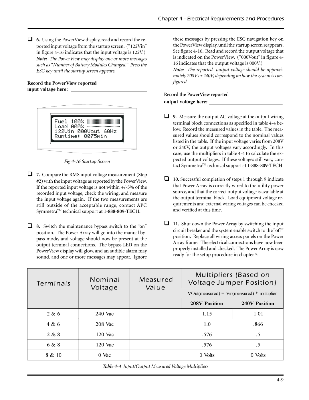
θ6. Using the PowerView display, read and record the re- ported input voltage from the startup screen. (“122Vin” in figure
Record the PowerView reported
input voltage here: ______________________________
Fig 4-16 Startup Screen
θ7. Compare the RMS input voltage measurement (Step #2) with the input voltage as reported by the PowerView. If the reported input voltage is not within
θ8. Switch the maintenance bypass switch to the “on” position. The Power Array will go into the manual by- pass mode, and voltage should now be present at the output terminal connections. The bypass LED on the PowerView display will glow, and an audible alarm may sound, and one or more messages may appear. Ignore
these messages by pressing the ESC navigation key on the PowerView display, until the startup screen reappears. See figure
Note: The reported output voltage should be approxi- mately 208V or 240V, depending on how the system is con- figured.
Record the PowerView reported
output voltage here: _____________________________
θ9. Measure the output AC voltage at the output wiring terminal block connections as specified in table
θ10. Successful completion of steps 1 through 9 indicate that Power Array is correctly wired to the utility power source, and that the correct output voltage is available at the output terminal block. Load equipment voltage re- quirements and external wiring voltages can be checked and verified at this time.
θ11. Shut down the Power Array by switching the input circuit breaker and the system enable switch to the “off ” position. Replace all wiring access panels on the Power Array frame. The electrical connections have now been properly installed and checked. The Power Array is now ready for the setup procedure in chapter 5.
Terminals
Nominal Voltage
Measured
Value
Multipliers (Based on Voltage Jumper Position)
VOut(measured) = Vin(measured) * multiplier
208V Position | 240V Position |
|
|
2 & 6 | 240 Vac |
| 1.15 | 1.01 |
|
|
|
|
|
4 & 6 | 208 Vac |
| 1.0 | .866 |
|
|
|
|
|
2 & 8 | 120 Vac |
| .576 | .5 |
|
|
|
|
|
6 & 8 | 120 Vac |
| .576 | .5 |
|
|
|
|
|
8 & 10 | 0 Vac |
| 0 Volts | 0 Volts |
|
|
|
|
|