Chapter 5 - System Setup
θ6. Press the down arrow key to scroll to the power mod- ule status screen. See figure
Fig 5-19 Power Status Screen
Verfiy that the number of power modules reported (3 in figure
Number | Reported | Reported |
of Power | Capacity in | Capacity in |
Modules | MiniFrame | MasterFrame |
|
|
|
1 | 4 kVA | 4 kVA |
|
|
|
2 | 8 kVA | 8 kVA |
|
|
|
3 | 8 kVA | 12 kVA |
|
|
|
4 | n/a | 16 kVA |
|
|
|
5 | n/a | 16 kVA |
|
|
|
Table 5-1 SymmetraTM Power Module/Frame Capacities
θ7. Press the down arrow key to scroll to the miscellaneous status screen. See figure
Fig 5-20 Miscellaneous Status Screen
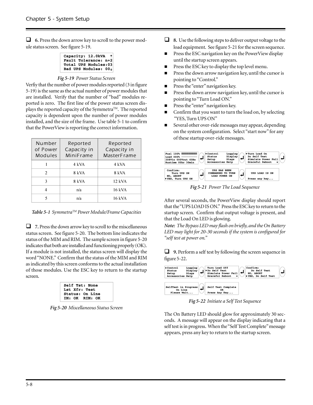
θ8. Use the following steps to deliver output voltage to the
load equipment. See figure
νPress the ESC navigation key on the PowerView display until the startup screen appears.
νPress the ESC key to display the top level menu.
νPress the down arrow navigation key, until the cursor is pointing to “Control.”
νPress the “enter” navigation key.
νPress the down arrow navigation key, until the cursor is pointing to “Turn Load ON.”
νPress the “enter” navigation key.
νConfirm that you want to turn the load on, by selecting “YES, Turn UPS ON”
νSeveral other
Fig 5-21 Power The Load Sequence
After several seconds, the PowerView display should report that the“UPS LOAD IS ON.” Press the ESC key to return to the startup screen. Confirm that output voltage is present, and that the Load On LED is glowing.
Note: The Bypass LED may flash on briefly, and the On Battery LED may light for
θ9. Perform a self test by following the screen sequence in figure
Fig 5-22 Initiate a Self Test Sequence
The On Battery LED should glow for approximately 30 sec- onds. A message will appear on the display indicating that a self test is in progress. When the“Self Test Complete”message appears, press any key to return to the startup screen.