NetLinx Integrated Controllers
AMX Limited Warranty and Disclaimer
Table of Contents
Installation and Upgrading
NetLinx Security with a Terminal Connection
Troubleshooting 125
NetLinx Integrated Master Controller Features
NI-2000 Specifications
NI-2000 Specifications
Rear Panel Components
Front Panel Components
D notation is used to explicitly represent a device number
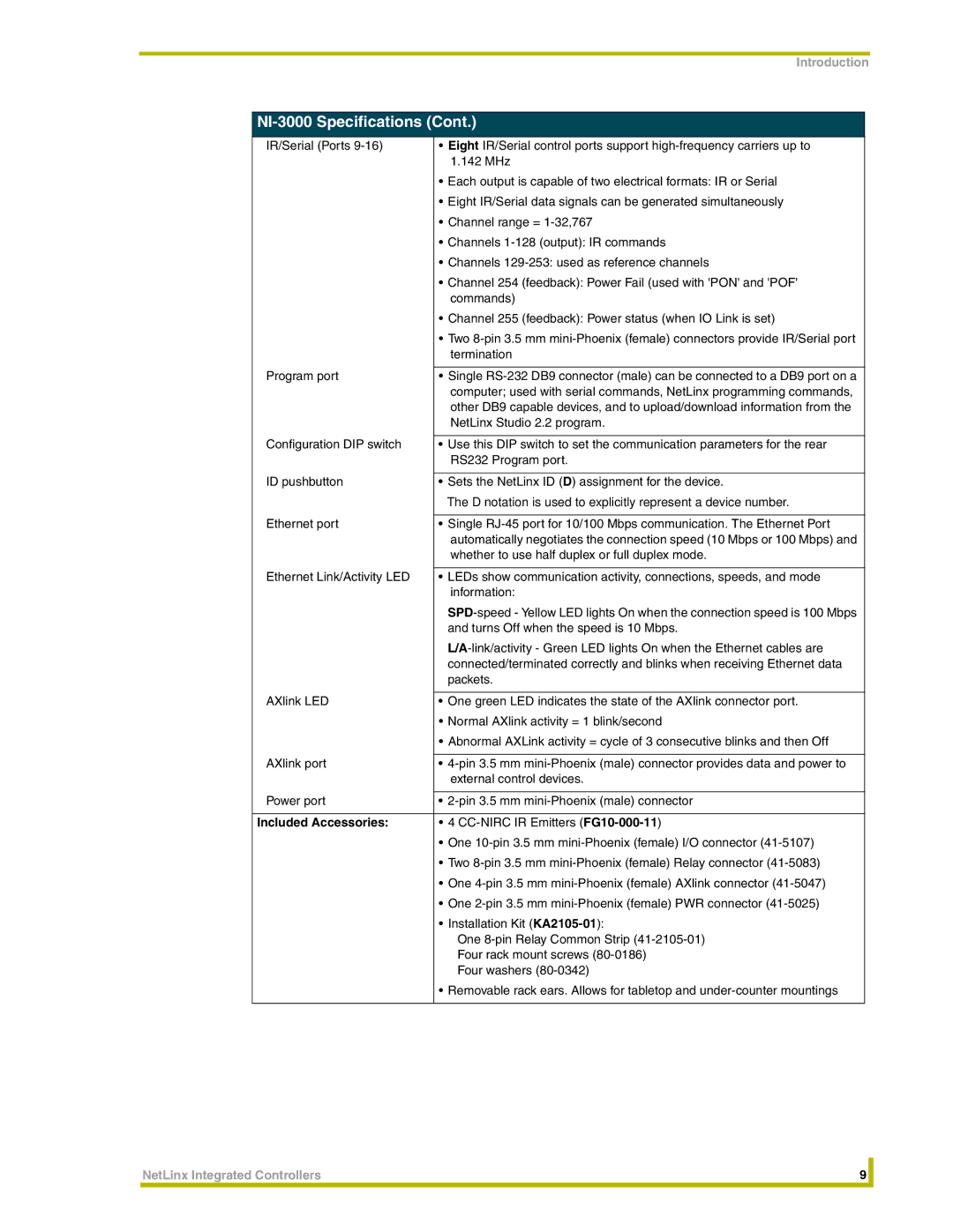
NI-3000 Specifications
Included Accessories
Optional Accessories
ICSNet AXLink LED RS-232/422/485 Ports ICSHub Out
Green
Relays IR/Serial Ports Ethernet AXLink Program
NI-3000 Specifications
Power requirements
Compact Flash
Rear Panel Components
Two 8-pin 3.5 mm mini-Phoenix female Relay connector
Whether to use half duplex or full duplex mode
Turns Off when the speed is 10 Mbps
One 10-pin 3.5 mm mini-Phoenix female I/O connector
NI-4000 NetLinx Integrated Controller front view
NI-4000 Specifications
NI-4000 Specifications
Rear Panel Components
D notation is used to explicitly represent a device number
Front/rear rack mounting
Pin Black Male Phoenix Connector 3.5mm
Two CC-NIRC IR Emitters FG10-000-11
Removable rack ears. Allows for tabletop, under-counter,
Configuration and Communication
Installation Procedures
IP recommended
Update the Controller and Control Card Firmware
Program NetLinx Security into the On-Board Master
Studio to the most recent release
Program Run Disable PRD mode
Setting the Configuration DIP Switch for the Program Port
Baud rate settings
Baud Rate Settings on the Configuration DIP Switch
Modes and LED Blink Patterns
Wiring Guidelines
Using the Configuration DIP switch
Modes and Front Panel LED Blink Patterns
Wiring Guidelines NI-2000 @ 700 mA
Preparing captive wires
Wiring length guidelines
Wiring Guidelines NI-4000 & NI-3000@ 900 mA
Local +12 VDC power supply coming from the PSN power supply
Using the 4-pin mini-Phoenix connector for data and power
AXlink/PWR connector
AXlink/PWR connector PWR + GND Top view
Program Port Connections and Wiring
RS-232/422/485 Device Port Wiring Specifications
Program Port, Pinouts, and Signals
RJ-45 Pinout Information EIA/TIA 568 B
ICSNet RJ-45 Connections/Wiring
RS-232/422/485 Device Port Wiring Specifications
ICSNet RJ-45 Signals
ICSHub OUT port
Ethernet 10/100 Base-T RJ-45 Connections/Wiring
ICSHub OUT Pinouts and Signals
Ethernet RJ-45 Pinouts and Signals
Ethernet Ports Used by the NetLinx Integrated Controllers
Relay Connections and Wiring
Ethernet LEDs
Ethernet ports used by the Integrated Controllers
Relay connections
Input/Output I/O Connections and Wiring
IR/Serial Connector Wiring Specifications
IR/Serial Connections and Wiring
Port Wiring Specifications NI-4000 and NI-3000
Port Wiring Specifications NI-2000
NetLinx Control Card 20-pin connector
NetLinx Control Card Slot Connector NI-4000 unit only
Connections and Wiring
Installing NetLinx Control Cards NI-4000 Only
Thumbscrews NXC Card Slot faceplate
Card slots Sample NXC cards Internal Guide slots
192 384 768 1536
Setting the NetLinx Control Card Addresses NI-4000 Only
DevicePortSystem DPS
Structure DEV
Removing NetLinx Control Cards NI-4000 Only
Compact Flash Upgrades
Optional Compact Flash Upgrades
Carefully Detach ALL Connectors from the rear of the unit
Installation of Compact Flash upgrades
Removing the Compact Flash card
Closing and Securing the Integrated Controller
Install screws Bracket Rack Mounting Holes
Installing the Integrated Controller into an Equipment Rack
Installation and Upgrading
Installation and Upgrading
Before beginning
Communicating with the Master via the Program Port
Setting the System Value
Select Diagnostics Device Addressing from the Main menu
Default setting for these units is
Using multiple NetLinx Masters
Device Addressing dialog changing the device value
Changing the Device Address on a NetLinx Device
Resetting the Factory Default System and Device Values
Recommended NetLinx Device numbers
Axcess Devices use Axcess standards
Used to assign an IP Address Used to obtain an
Obtaining the Master’s IP Address using Dhcp
Select Diagnostics Network Addresses from the Main menu
Assigning a Static IP to the NetLinx Master
Used to assign an IP Address
Communicating with the On-board Master via an IP
Assigning Communication Settings and TCP/IP Settings
Upgrading the On-board Master Firmware via an IP
Verifying the current version of NetLinx Master Firmware
Selected on-board Master Firmware file
Firmware download status
Device and System Number
Upgrading the NI Controller Firmware via an IP
Sample NetLinx Workspace window
Upgrading the new NI Controller firmware via an IP
Firmware file NIX000 Firmware download status
Selected Integrated Controller
Upgrading the Control Card Firmware via an IP
Firmware file Firmware download status
Selected Control Card
Safari Yes
NetLinx Security web browser and feature support
Supported Browser and Feature Compatibility
OS Platform
New Master Firmware Security Features
NetLinx Security Terms
NetLinx Security Terms
WebControl Tab
Accessing the NetLinx Master via its IP Address
Default Security Configuration
WebControl Tab Features
Default Security Configuration
Groups section
Security Tab Features
Feature Description System section
Security Tab
Security System Features
Security tab Enable Security
Add Group Entries
Administrator’s user passwords
Default password can no longer be used to gain access
Security tab Add Group
Modify Group Entries
Security tab Modify Group
Security tab Group Directory Associations
Valid Directory Association Entries
Group Directory Association Entries
Path Description
Sensitive and must be unique
Security Config Access
Security tab Add User
Add User Entries
Modify User Entries
Security tab Modify User
Must be unique
Security tab User Directory Associations
New user is selected
Enables access to the user directory and all files
User Directory Association Entries
Subdirectories in that user directory
Security tab SSL Server Certificate
Server Certificate Entries
Common Name can not be an IP Address
Previous fields and generates its own SSL Certificate
Information from the certificate currently installed on
Is an alpha-numeric string 1 50 characters in length
Create Request Takes the information entered into
Security tab Import Certificate
Security tab Export Certificate Request
System Tab
Show Devices Tab
Network Tab
Security tab showing NetLinx Master security options
Master Security Setup Procedures
Security tab showing the Add Group fields
Adding a Group and assigning their access rights
Security tab showing the Modify Group access rights fields
Modifying an existing Group’s access rights
Deleting an existing Group
Showing a list of authorized Groups
Security tab showing the Group Directory Associations fields
Adding a Group directory association
Confirming the new directory association
Click the Directory Associations link
Deleting a directory association
NetLinx cannot be used since they already exist
Adding a User and configuring their access rights
Security tab showing the Modify User Configurations fields
Modifying an existing User’s access rights
Deleting a User
Showing a list of authorized Users
Security tab showing the User Directory Associations fields
Adding a User directory association
SSL Certificate Procedures
City/province name must be fully spelled out
Self-Generating a SSL Server Certificate Request
State/province name must be fully spelled out
Creating a Request for a SSL Server Certificate
YOU can not Request Another Certificate Until the Previous
Before importing a CA server certificate, you must
Regenerating an SSL Server Certificate Request
Display SSL Server Certificate Information
Before exiting the Master and beginning another session
Common Steps for Requesting a Certificate from a CA
NetLinx Security and Web Server
Security Alert and Certificate popups
Accessing an SSL-Enabled Master via an IP Address
Click Next to proceed with the certificate storage process
G3 panel G4 panel
Using your NetLinx Master to control the G4 panel
WebControl VNC installation and Password entry screens
Using your NetLinx Master to control the G3 panel
What to do when a Certificate Expires
Establishing a Terminal connection
NetLinx Security Features
Initial Setup via a Terminal Connection
NetLinx Security Features
Stop bits1, and Flow control None default is Hardware
Accessing the Security configuration options
Terminal
Option 3 Add user
Command Description
Security Options Menu
Option 2 Display system security options for NetLinx Master
Edit User Menu
Option 4 Edit User
Edit User Menu
Option 7 Add Group
Access Rights Menu
Option 5 Delete user
Option 6 Show the list of authorized users
Path
Subdirectories in the user directory
Granted to that file
Edit Group menu Delete directory association
Option 9 Delete Group
Option 8 Edit Group
Option 13 Make changes permanent by saving to flash
Option 11 Set Telnet Timeout in seconds
Option 12 Display Telnet Timeout in seconds
Option 10 Show List of Authorized Groups
Main Security Menu
Main Security Menu
Command
Help Menu Options
Help menu
Logging Into a Session
Setup Security
Logout
Help Security
Using the ID Button
Converting Axcess Code to NetLinx Code
DevicePortSystem DPS
Program Port Commands
PC COM Port Communication Settings
Program Port Commands
MEM
Reboot DPS
Sendcommand
GET IP DPS
Show Device DPS
SET IP DPS
SET Time
SET URL DPS
+ + ESC ESC
ESC Pass Codes
Escape Pass Codes
WindowsTM client programs
Linux Telnet client
LED Disable/Enable SendCommands
RS-232/422/485 SendCommands
RS232/422/485 Ports Channels
Sendcommand RS2321,CHARDM10
Sendcommand DEV,B9MON
Sendcommand RS2321,B9MON
Sendcommand RS2321,CHARD10
Sendcommand RS2321,RXCLR
Sendcommand DEV,HSON
Sendcommand RS2321,HSON
Sendcommand DEV,RXCLR
RS-232/422/485 SendString Escape Sequences
RS-232/422/485 SendString Escape Sequences
IR RX Port Channels
IR/Serial SendCommands
IR/Serial SendCommands
IR / Serial Ports Channels
Sendcommand IR1,CTON,20
Sendcommand IR1, CH,18
Sendcommand IR1,CP,2
Sendcommand IR1,CTOF,10
Sendcommand IR1,IROFF
Sendcommand DEV, GET Mode
Sendcommand IR1,GET Mode
Sendcommand DEV,IROFF
Sendcommand IR1, SET Mode IR
Sendcommand IR1, PTOF,15
Sendcommand IR1, PTON,15
Sendcommand IR1, SET IO Link
Sendcommand IR1, XCH
Sendcommand IR1,XCHM
Sendcommand IO,SET Input 1 High
Input/Output SendCommands
Sendcommand DEV,GET Input Chan
Sendcommand IO,GET Input
Programming 124
Troubleshooting Information
SET Ethernet Mode 100 Full
SET Ethernet Mode 10 Half
SET Ethernet Mode 10 Full
SET Ethernet Mode 100 Half
Process, NetLinx Studio failed to
Symptom Solution During the firmware upgrade
Install the last component
IP section on page 46 for detailed procedures
RevisionLast12/10/04