Operators Manual
ALS 230
8.3.3APSF sensor
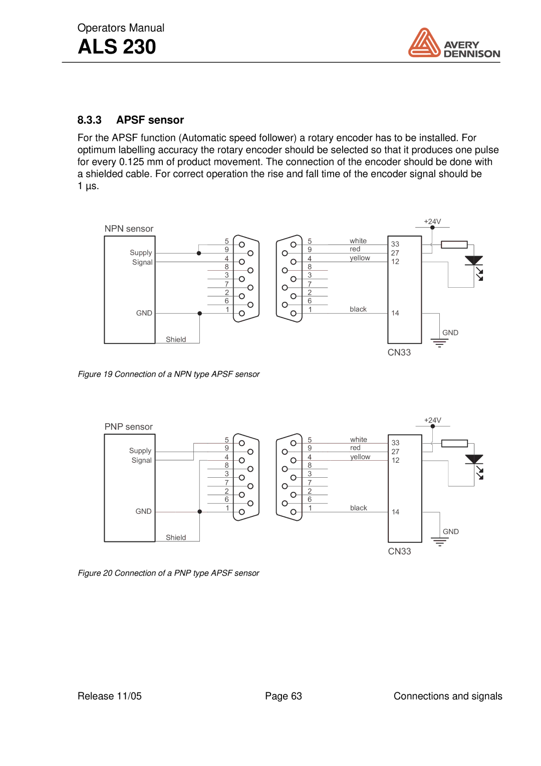
For the APSF function (Automatic speed follower) a rotary encoder has to be installed. For optimum labelling accuracy the rotary encoder should be selected so that it produces one pulse for every 0.125 mm of product movement. The connection of the encoder should be done with a shielded cable. For correct operation the rise and fall time of the encoder signal should be
1 µs.
NPN sensor
Supply
Signal
GND
5
9
4
8
3
7
2
6
1
Shield
5 | white |
9 | red |
4yellow
1black
+24V
33
27
12
14
GND
CN33
Figure 19 Connection of a NPN type APSF sensor
PNP sensor
| 5 |
| |||
Supply |
| 9 |
| ||
| 4 |
| |||
Signal |
|
| |||
|
|
| 8 |
| |
|
|
| |||
|
|
| 3 |
| |
|
|
| 7 |
| |
|
|
| 2 |
| |
|
|
| 6 |
| |
GND |
| 1 |
| ||
| Shield |
|
|
| |
Figure 20 Connection of a PNP type APSF sensor
| 5 | white |
| 9 | red |
4yellow
1black
+24V
33
27
12
14
GND
CN33
Release 11/05 | Page 63 | Connections and signals |
