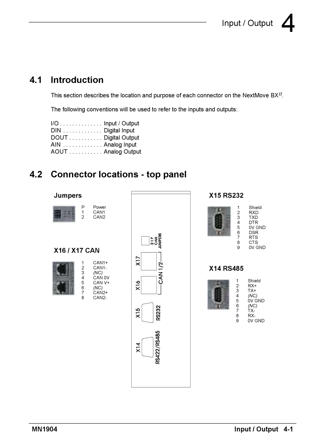
BXII specifications
The Baldor BXII is a robust and versatile industrial motor known for its high performance and reliability in various applications. Designed for use in demanding environments, the BXII series is particularly favored in the food processing, petrochemical, and material handling industries. Its construction and technological features distinctly differentiate it from other motors in the market, enhancing efficiency and durability.One of the standout features of the Baldor BXII is its premium efficiency rating, which ensures that the motor operates with minimal energy loss. This efficiency is crucial for industries looking to reduce energy costs and lower environmental impact. The BXII motor meets or exceeds NEMA Premium Efficiency standards, making it an eco-friendly choice for operations requiring continuous power.
Another important characteristic of the BXII series is its advanced design, featuring a high-quality aluminum frame that promotes excellent heat dissipation. This construction enhances the lifespan of the motor and reduces the risk of overheating during extended operation. Additionally, the BXII is equipped with an IP55-rated enclosure, ensuring that it is well-protected against dust and moisture, which is vital for reliability in harsh environments.
The Baldor BXII incorporates state-of-the-art technology in its motor design, including an innovative rotor design that offers optimal torque characteristics. This carefully engineered rotor ensures smooth operation and minimal vibration, resulting in increased performance and reduced wear on mechanical components.
Moreover, the BXII series employs a continuous duty service factor, allowing for longer operational hours without overheating or compromising performance. This is particularly beneficial for applications requiring consistent power output over extended periods.
The integration of smart technologies in the BXII line also enhances its usability. Features such as thermal protection and vibration sensors enable proactive monitoring of motor health, leading to preemptive maintenance that reduces downtime and extends the life of the motor.
Overall, the Baldor BXII offers a winning combination of efficiency, durability, and advanced technology, making it a reliable choice for industrial applications. Its commitment to performance and innovation underscores Baldor's reputation as a leader in the manufacturing of high-quality motors, ensuring that businesses can operate with confidence and efficiency. Whether in a food processing facility or a manufacturing plant, the BXII series stands out as an exemplary choice for those seeking dependable motor solutions.

