Location and Functions of Control
2 |
| LOCATION AND FUNCTION OF CONTROLS | |
| |||
|
|
| |
|
|
|
|
|
|
|
|
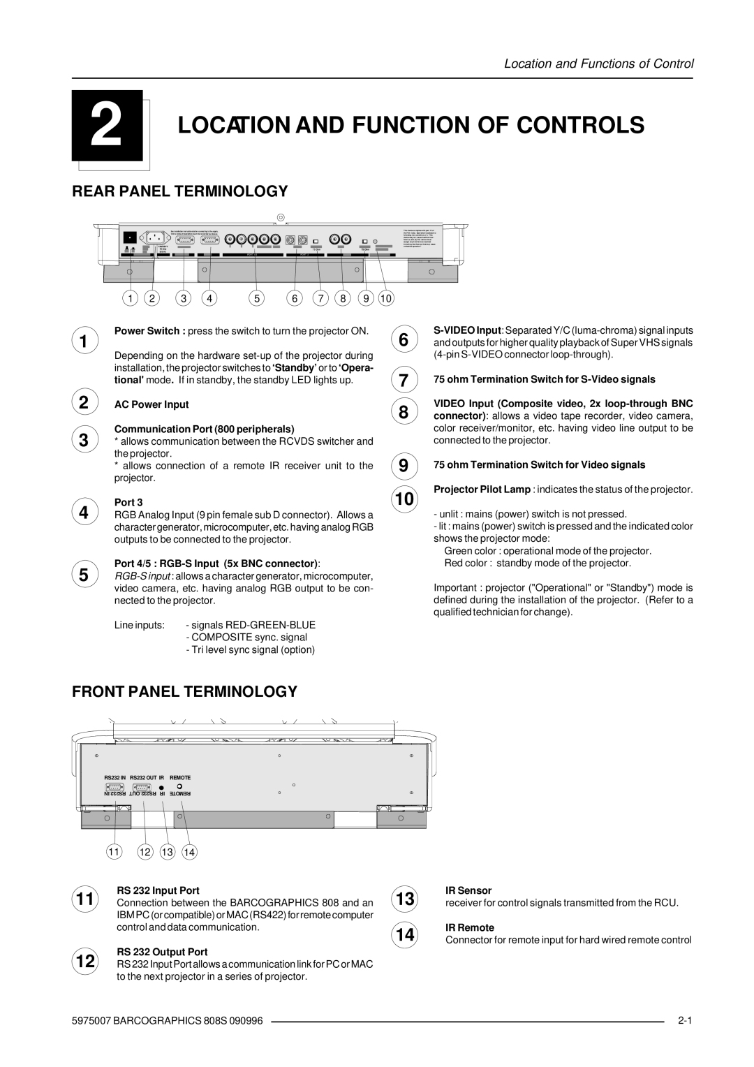
REAR PANEL TERMINOLOGY | |||
See installation i nstructions before connecting to the supply.
Voir la notice d'installation avant de raccorder au réseau.
120/230 V |
|
|
7/5 Amp | 7 5 Ohm | 75 Ohm |
50/60 Hz |
|
|
PORT 4/5 | PORT 2 |
|
This device co mplies with part 15 of the FCC rules. Oper ation is sub ject to following two conditions ( 1). This device may no t cause h armful inter- feren ce, and (2) this device must accep t any in terferen ce received including interference that may cause undesired operation"
1 2 3 4 5 6 7 8 9 10
1 | Power Switch : press the switch to turn the projector ON. | 6 | ||
Depending on the hardware | ||||
|
| |||
| installation, the projector switches to ‘Standby’ or to ‘Opera- | 7 | ||
| tional'mode. If in standby, the standby LED lights up. | |||
2 | AC Power Input | 8 | ||
|
|
| ||
3 | Communication Port (800 peripherals) |
| ||
* allows communication between the RCVDS switcher and |
| |||
| the projector. |
| 9 | |
| * allows connection of a remote IR receiver unit to the | |||
| projector. |
|
| |
4 | Port 3 |
| 10 | |
RGB Analog Input (9 pin female sub D connector). Allows a |
| |||
| character generator, microcomputer, etc. having analog RGB |
| ||
| outputs to be connected to the projector. |
| ||
5 | Port 4/5 : |
| ||
| ||||
| video camera, etc. having analog RGB output to be con- |
| ||
| nected to the projector. |
| ||
| Line inputs: | - signals |
| |
|
| - COMPOSITE sync. signal |
| |
|
| - Tri level sync signal (option) |
| |
75 ohm Termination Switch for
VIDEO Input (Composite video, 2x
75 ohm Termination Switch for Video signals
Projector Pilot Lamp : indicates the status of the projector.
-unlit : mains (power) switch is not pressed.
-lit : mains (power) switch is pressed and the indicated color shows the projector mode:
Green color : operational mode of the projector.
Red color : standby mode of the projector.
Important : projector ("Operational" or "Standby") mode is defined during the installation of the projector. (Refer to a qualified technician for change).
FRONT PANEL TERMINOLOGY
RS232 IN | RS232 OUT IR | REMOTE | ||
IN RS232 OUT RS232 IR | REMOTE | |||
11 | 12 | 13 | 14 | |
11
12
RS 232 Input Port
Connection between the BARCOGRAPHICS 808 and an IBM PC (or compatible) or MAC (RS422) for remote computer control and data communication.
RS 232 Output Port
RS 232 Input Port allows a communication link for PC or MAC to the next projector in a series of projector.
13
14
IR Sensor
receiver for control signals transmitted from the RCU.
IR Remote
Connector for remote input for hard wired remote control
5975007 BARCOGRAPHICS 808S 090996 |
| |
|