Random Access Adjustment Mode
Raster Shift Adjustment
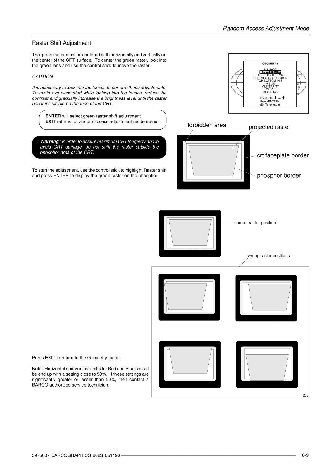
The green raster must be centered both horizontally and vertically on the center of the CRT surface. To center the green raster, look into the green lens and use the control stick to move the raster.
CAUTION
It is necessary to look into the lenses to perform these adjustments. To avoid eye discomfort while looking into the lenses, reduce the contrast and gradually increase the brightness level until the raster becomes visible on the face of the CRT.
ENTER will select green raster shift adjustment
EXIT returns to random access adjustment mode menu.
Warning : In order to ensure maximum CRT longevity and to avoid CRT damage, do not shift the raster outside the phosphor area of the CRT.
To start the adjustment, use the control stick to highlight Raster shift and press ENTER to display the green raster on the phosphor.
GEOMETRY |
|
H PHASE |
|
RASTER SHIFT | |
LEFT SIDE CORRECTION | |
H SIZE |
|
V LINEARITY | |
V SIZE |
|
BLANKING |
|
Select with | or |
then <ENTER> | |
<EXIT> to return. | |
forbidden area | projected raster |
|
crt faceplate border |
phosphor border |
correct raster position
wrong raster positions
Press EXIT to return to the Geometry menu.
Note : Horizontal and Vertical shifts for Red and Blue should be end up with a setting close to 50%. If these settings are significantly greater or lesser than 50%, then contact a BARCO authorized service technician.
233 |
5975007 BARCOGRAPHICS 808S 051196 |
| |
|