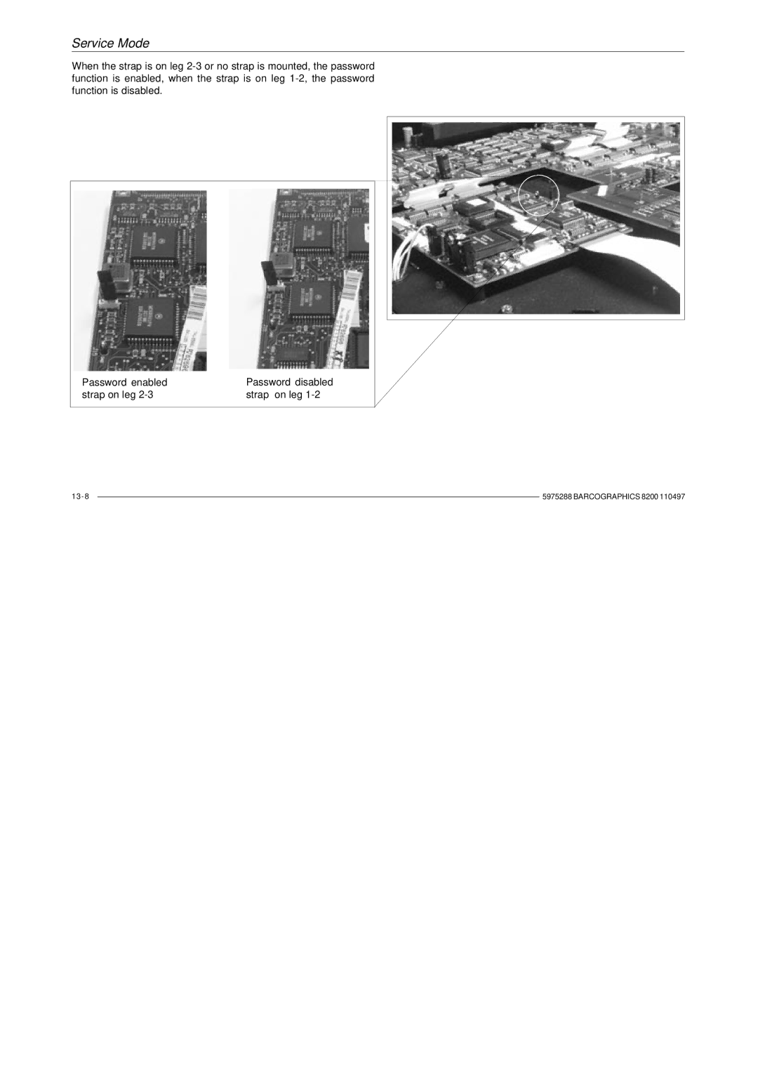
R9001330
BARCO PROJECTION SYSTEMS GRAPHICS
OWNERS MANUAL
Trademarks are the rights of their respective owners
Produced by BARCO NV, April All rights reserved
Printed in Belgium
Table of Contents
How to program an address into the RCU?
Table of Contents
Set up of the baud rate for communication with a computer
How to display a projector address?
Table of Contents
Hardwired RCU
Table of Contents
On installation
Safety Instructions
Safety instructions
On safety
DONNEES POUR LE PROPRIETAIRE
Instructions pour l’installation
Prescription de sécurtié
Remarque sur la Sécurité
PART NUMBER SER. NUMBER DEALER
Notice on safety
Installation instructions
OWNER’S RECORD
Prescription de sécurtié
Fédéral communication commission FCC statement
Le point d’exclamation dans un triangle indique
Safety Instructions
Federal communication commission FCC statement
B. Cordon d’alimentation avec connecteur ANSI
Prescriptions de securite générales
SECURITE
A. Cordon d’alimentation avec connecteur CEE7
B. Power cord with ANSI 73.11 plug
General safety instructions
ON SAFETY
A. Mains lead AC Power cord with CEE 7 plug
Prescription de sécurtié
L’Installation
Les fentes et les ouvertures pourvues dans le boîtier et au dos ou
Safety Instructions
On Installation
Slots and openings in the cabinet and the sides are provided for
Page
Call for service in the following conditions
On Cleaning
On Servicing
Safety Instructions
Eclairage
To ensure the highest optical performance and resolution, the projection lenses are specially treated with an anti-reflective coating, therefore avoid touching the lens. To remove dust on the lens, use a soft dry cloth. Do not use a damp cloth, detergent solution, or thinner. Follow the lens cleaning procedure on Appendix D in the Owners Manual
On Repacking
On illumination
Safety Instructions
UNPACKING DIMENSIONS BATTERY INSTALLATION ON THE RCU
Unpacking & Dimensions
Unpacking
Pull To open
Unpacking & Dimensions
Projector dimensions
Unpacking & Dimensions
Battery installation in the RCU
Environment What about ambient light? Which screen type?
Installation Guidelines
INSTALLATION GUIDELINES
How to install the projector?
Installation Guidelines
Installation guidelines
Environment
What about ambient light ?
Screen width
Which screen type?
What image size? How big should the image be?
Installation Guidelines
Lens type selection
Where to install the projector?
Inputs and computer video format input compatibility
Definitions of the Abbreviation on drawings
CD = B - A
Ceiling mounting of the BARCOGRAPHICS
Table mounting of the BARCOGRAPHICS
Installation Guidelines
How to install a projection lens?
How to install the projector?
BARCO projection table
INSTALLATION SET UP
Installation Set Up
Projector configuration
Rear/Ceilin g Rear/T ab l e
Installation Set Up
F ro n t/Ceilin g F ro n t/T able
INSTALLATION
ENTER
Installation Set Up
ADJUSTMENT MODE
Location and Functions of Control
Front panel terminology Local keypad Remote control
LOCATION AND FUNCTION OF CONTROLS
Front panel terminology
Diagnostics code a source number
Location and Functions of Control
b. Remote control
Control Panel Terminology
a. Local keypad
E N T E R
Remote Control RCU
Location and Functions of Control
Local keypad
key down
Terminology
Control disk on RCU or + and - keyscursor keys to
Location and Functions of Control
POWER CONNECTION
Power Connection
Power Connection
Power mains cord connection
Switching on
Fuses
To start image projection
Power Connection
Switching off
Switching to stand-by
Power Connection
INPUT MODULE CONNECTIONS
Connecting a computer Connecting a RCVDS05 Connecting a VS05
Connecting an IR Remote Receiver
Connections
Input module insertion into the projector
Input connections
Connections
Connections
Video/S-video input module
Connections
EXIT returns to operational mode
Floating or non-floating input Video input
Straps on module level
Factory preset strap on, input non floating
Connections
Connections
RGB analog input module
Straps on module level
RGB input selection
Connections
Key in the corresponding slot number on the RCU or the local keypad
Connections
Push the control disk up or down to select Installation and press
ENTER
Connections
Component input module
Straps on module level
Component input selection
Indication on the input slot menu
Connections
Indication on the input slot menu
RGB3S/RG3sB input module
Input selection
Connections
Straps on module level
Connections
See Change Baudrate PC in chapter Service mode
Set up of the baud rate for communication with a computer
Connections
Connections
Connecting a RCVDS 05 to the projector
Connecting an IR Remote Receiver 800 to the projector
Connecting a VS05 to the projector
Picture controls with direct access
How to use the RCU Projector address
How to display a projector address
How to program an address into the RCU
Controlling
How to use the RCU?
Projector address
a. Software set up of the projector address
b. How to control the projector or projectors
c. Using the RCU
Brightness Control
How to display a projector address?
How to program an address into the RCU?
Picture controls with direct access
Sharpness Control
Phase Control
Contrast Control
Color Saturation
START UP OF THE ADJUSTMENT MODE
Start Up of the Adjustment Mode
Source Select with or then ENTER EXIT to return
Adjustment Mode
Start Up of the Adjustment Mode
Select a path from below GUIDED RANDOM ACCESS INSTALLATION SERVICE
Your password contains 4 digits
Start Up of the Adjustment Mode
GUIDED ADJUSTMENT MODE
Guided Adjustment Mode
GUIDED
Guided Adjustment Mode
The Guided Adjustment Mode is not active
ADJUSTMENT MODE
RANDOM ACCESS ADJUSTMENT MODE
Random Access Adjustment Mode
File Service Picture Tuning Geometry
ADJUSTMENT MODE
Starting up the Random Access Adjustment Mode
Random Access Adjustment Mode
RANDOM ACCESS ADJUSTMENT MODE
Random Access Adjustment Mode
File service
Random Access Adjustment Mode
Load file
Random Access Adjustment Mode
Edit file
ENTER
Random Access Adjustment Mode
Read AMDS
Random Access Adjustment Mode
Options
EDIT FILE OPTIONS
Vertical sync polarity leading or trailing
Random Access Adjustment Mode
Rename
Random Access Adjustment Mode
Copy
COPY FILE
Random Access Adjustment Mode
Delete
File Options
Picture Tuning
Random Access Adjustment Mode
Still Video
Sync slow/fast
Random Access Adjustment Mode
Color Balance
GAMMA
Gamma
Random Access Adjustment Mode
PICTURE TUNING
ENTER
Geometry
Shift
Random Access Adjustment Mode
Size
Random Access Adjustment Mode
Side keystone
SIDE KEYSTONE
Random Access Adjustment Mode
Blanking
BLANKING
Random Access Adjustment Mode
TOP BOTTOM LEFT RIGHT Select with or then ENTER EXIT to return
Random Access Adjustment Mode
Options
INSTALLATION
Installation
Convergence Configuration Internal Patterns
Installation
Starting up the Installation Mode
Component Video - SOY component video
Input Slots
Installation
ENTER
Installation
Convergence
Convergence and press ENTER to
Green focusing
Installation
Installation
Red on green convergence
If both lines are correctly converged, continue with screw
Installation
Installation
Blue on green convergence
Internal Patterns
Configuration
Installation
Change Projector Address Change Baudrate PC Reset Lamp Run Time
Service Mode
SERVICE MODE
Identification Change Password Change Language
Service Mode
Starting up the Service Mode
ENTER
CHANGE PASSWORD
Service Mode
SERVICE
SERVICE
PRESET INPUT BALANCE
Service Mode
SERVICE
PANEL ADJUSTMENT RED COARSE
software version
Identification
Service Mode
nication with a computer in chapter Connections
Service Mode
How to enable or disable the password function ?
Change Password
Service Mode
strap on leg
Service Mode
Password enabled
Password disabled
Change Language
How to change the password ?
Service Mode
Change Baudrate PC
Change Projector Address
Service Mode
Service Mode
Reset Lamp Runtime
ENTER
Lamp Run Time History
Service Mode
SERVICE
Service Mode
Panel Adjustments
Service Mode
Preset Input Balance
Service Mode
60 Hz Tracking
I2C DIAGNOSIS
I2C diagnosis
Service Mode
SERVICE
MAGIK interface Adapter and communication cables
OPTIONAL EQUIPMENT IR remote receiver Hardwired RCU RCVDS05 VS05
Mechanical shutter Adjustable lensholder
Optional Equipment
shield conductor
Hardwired RCU
IR Receiver
Optional Equipment
VS05
RCVDS 800 / RCVDS
Optional Equipment
Optional Equipment
MAGIK Interface
Adapter and communication cables
a. D9-D9 communication cable
d. 5 BNC to 5 BNC cable
Ceiling Mount Kit CM100
b. Din Mini8-D9 adapter cable
c. D25-D9 adapter cable
Projector Transport Handle
Projector Frame for Dual or Triple Configurations
Optional Equipment
Multifunctional flight case
Features
Optional Equipment
Mechanical Shutter
Adjustable lensholder
Optional Equipment
Standard source set up files
Appendix A Standard Source Set Up Files
Battery replacement in the RCU
Appendix B Battery Replacement in the RCU
Focusing the lens
Appendix C Focusing the Lens
Lens holder Fastener Lens
Cleaning procedure for the other HD lens
Appendix D Lens Cleaning Procedure
Lens Cleaning Procedure
Cleaning procedure for HD1.5-31 lens and HD3-5.31 lens
the lens. Wipe at a speed that is equal to the evaporation rate. This is very important to prevent streaking and spotting. Start your wiping at one side of the lens and, with successive wipes, move to the other side. Turn the pad over for each wipe, then inside out. Do not make more than one wipe per clean area of pad. Be careful of the painted edge, since acetone will soften it
Appendix D Lens Cleaning Procedure
Source numbers 90
Appendix E Source Number 90
HD2.21
Appendix F Lenses
Lenses
HD1.21
Appendix F Lenses
Lens formulas to calculate the projector distance
INPUT SOURCES
Insert card RCU
R C U
R C U