Optional Equipment
IR Receiver 800
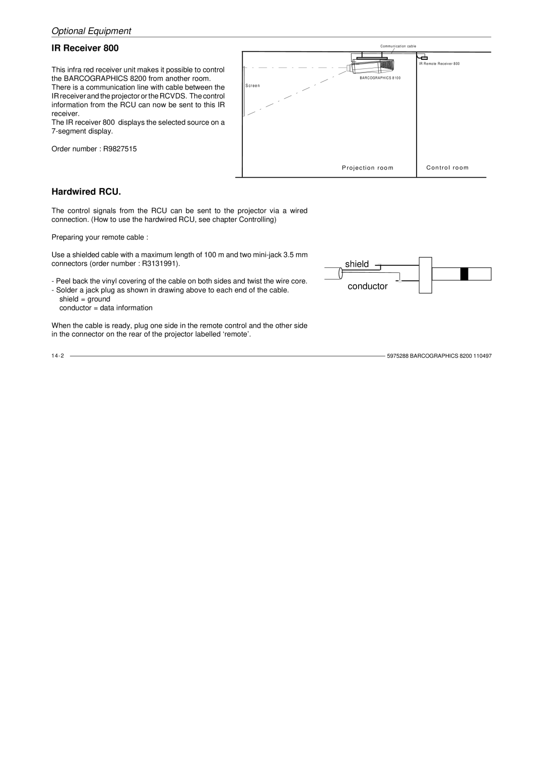
This infra red receiver unit makes it possible to control the BARCOGRAPHICS 8200 from another room. There is a communication line with cable between the IR receiver and the projector or the RCVDS. The control information from the RCU can now be sent to this IR receiver.
The IR receiver 800 displays the selected source on a
S c r e e n
Communication cable
IR Remote Receiver 800
BARCOGRAPHICS 8100
Order number : R9827515
Projection room | Con trol r oom |
Hardwired RCU.
The control signals from the RCU can be sent to the projector via a wired connection. (How to use the hardwired RCU, see chapter Controlling)
Preparing your remote cable :
Use a shielded cable with a maximum length of 100 m and two
-Peel back the vinyl covering of the cable on both sides and twist the wire core.
-Solder a jack plug as shown in drawing above to each end of the cable. shield = ground
conductor = data information
When the cable is ready, plug one side in the remote control and the other side in the connector on the rear of the projector labelled ‘remote’.
shield
conductor
| 5975288 BARCOGRAPHICS 8200 110497 | |
| ||
|
|
|