102 en | LTC 8600 LTC 8800 Series |
22 Troubleshooting Guide
The Allegiant system has been designed to perform reliably for long periods of time. All circuitry consists of
22.1Main Bay Checkout
1.Main power switch is ON and power LED indicator is not lit: Check main line fuse on rear of main bay. Refer to Maintenance Information Section for replace- ment instructions.
2.Any of the green LED indicators located on the front of the main power supply is out: Replace blown fuses associated with any unit fuse indicators.
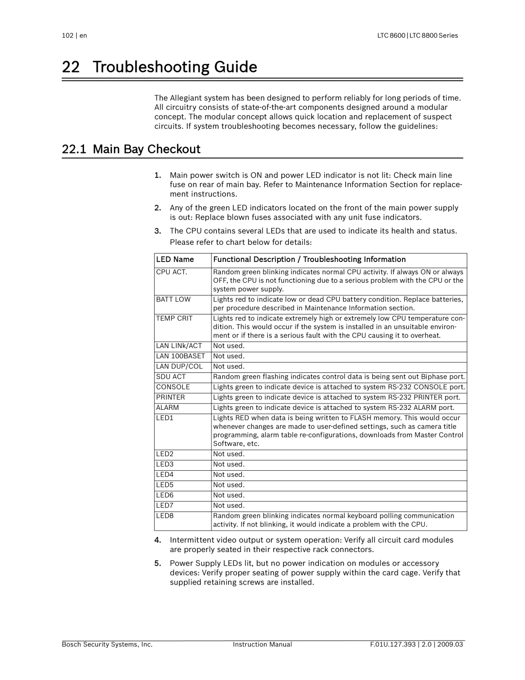
3.The CPU contains several LEDs that are used to indicate its health and status. Please refer to chart below for details:
LED Name | Functional Description / Troubleshooting Information |
|
|
CPU ACT. | Random green blinking indicates normal CPU activity. If always ON or always |
| OFF, the CPU is not functioning due to a serious problem with the CPU or the |
| system power supply. |
|
|
BATT LOW | Lights red to indicate low or dead CPU battery condition. Replace batteries, |
| per procedure described in Maintenance Information section. |
|
|
TEMP CRIT | Lights red to indicate extremely high or extremely low CPU temperature con- |
| dition. This would occur if the system is installed in an unsuitable environ- |
| ment or if there is a serious fault with the CPU causing it to overheat. |
|
|
LAN LINk/ACT | Not used. |
|
|
LAN 100BASET | Not used. |
|
|
LAN DUP/COL | Not used. |
|
|
SDU ACT | Random green flashing indicates control data is being sent out Biphase port. |
|
|
CONSOLE | Lights green to indicate device is attached to system |
|
|
PRINTER | Lights green to indicate device is attached to system |
|
|
ALARM | Lights green to indicate device is attached to system |
|
|
LED1 | Lights RED when data is being written to FLASH memory. This would occur |
| whenever changes are made to |
| programming, alarm table |
| Software, etc. |
|
|
LED2 | Not used. |
|
|
LED3 | Not used. |
|
|
LED4 | Not used. |
|
|
LED5 | Not used. |
|
|
LED6 | Not used. |
|
|
LED7 | Not used. |
|
|
LED8 | Random green blinking indicates normal keyboard polling communication |
| activity. If not blinking, it would indicate a problem with the CPU. |
|
|
4.Intermittent video output or system operation: Verify all circuit card modules are properly seated in their respective rack connectors.
5.Power Supply LEDs lit, but no power indication on modules or accessory devices: Verify proper seating of power supply within the card cage. Verify that supplied retaining screws are installed.
Bosch Security Systems, Inc. | Instruction Manual | F.01U.127.393 2.0 2009.03 |
