LTC 8600 LTC 8800 Series | en 31 |
|
|
eras, numbers 97 through 128) should be attached to the main bay connectors labeled “VIDEO
The LTC 8600 Series system is supplied with one LTC 8808/00 (patch panel plus two (2) TC8809 ribbon cables). This should be installed on the rear of the racking equipment to permit immediate or future connections of camera inputs 97 through 128.
A LTC 8808/00 Patch Panel must be ordered separately for each group of 32 cam- eras above 96 that will be connected to an LTC 8800 Series system.
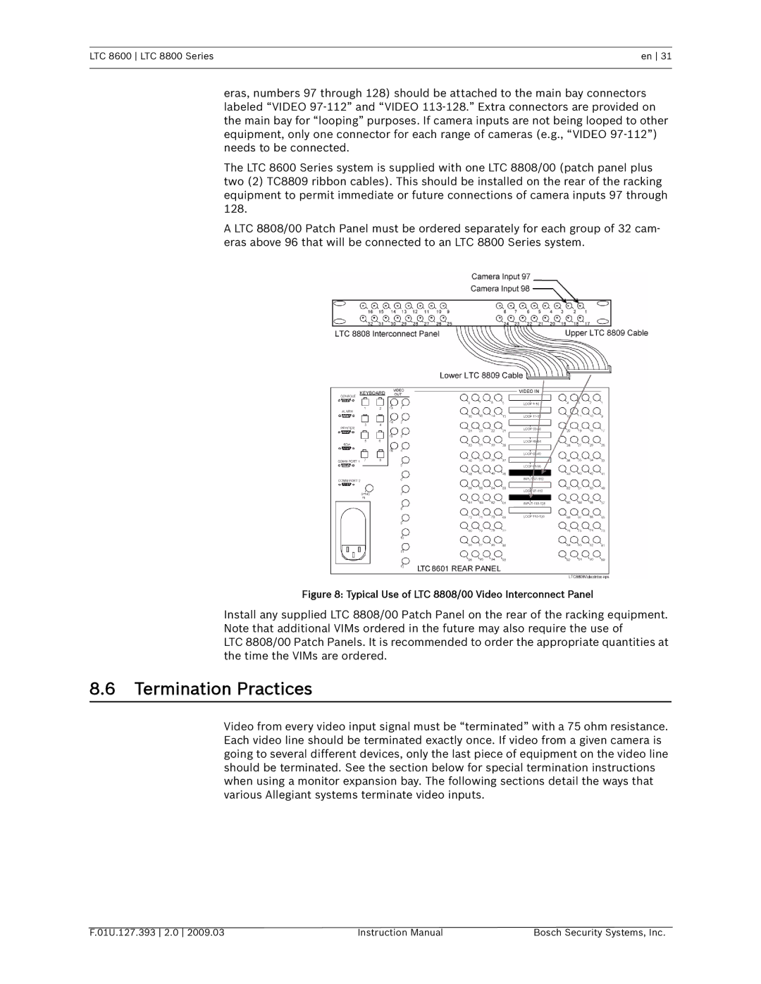
Figure 8: Typical Use of LTC 8808/00 Video Interconnect Panel
Install any supplied LTC 8808/00 Patch Panel on the rear of the racking equipment. Note that additional VIMs ordered in the future may also require the use of
LTC 8808/00 Patch Panels. It is recommended to order the appropriate quantities at the time the VIMs are ordered.
8.6Termination Practices
Video from every video input signal must be “terminated” with a 75 ohm resistance. Each video line should be terminated exactly once. If video from a given camera is going to several different devices, only the last piece of equipment on the video line should be terminated. See the section below for special termination instructions when using a monitor expansion bay. The following sections detail the ways that various Allegiant systems terminate video inputs.
F.01U.127.393 2.0 2009.03 | Instruction Manual | Bosch Security Systems, Inc. |