22 en Installation | VideoJet X40 SN |
|
|
Relay Outputs
The VideoJet X40 SN has four relay outputs for switching external units such as lamps or alarm sirens. You can operate these relay outputs manually while there is an active connection to the VideoJet X40 SN. The outputs can also be configured to automatically activate sirens or other alarm units in response to an alarm signal. The relay outputs are also located on the orange terminal block (see Section 8.8 Terminal Block, page 115).
! | CAUTION! | |
A maximum load of 30 V and 2 A (SELV) may be applied to the relay contacts. | ||
|
X Connect the lines to the appropriate terminals on the orange terminal block (R1 to R4) and check that the connection is secure.
Remote Indication of the Connection Status
When the VideoJet X40 SN is connected to a video, the Connect LED on the front panel of the unit flashes. The LED also provides information on the operational state of the unit and signals a unit defect (see Section 8.4 LEDs, page 113).
You can connect an additional
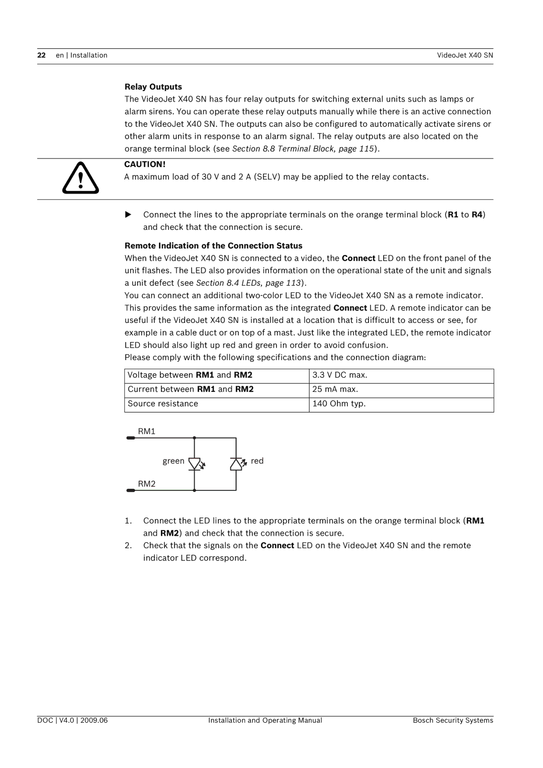
Please comply with the following specifications and the connection diagram:
Voltage between RM1 and RM2 | 3.3 V DC max. | |||||||
|
|
|
|
|
|
|
|
|
Current between RM1 and RM2 | 25 mA max. | |||||||
|
|
|
|
|
|
|
|
|
Source resistance | 140 Ohm typ. | |||||||
|
|
|
|
|
|
|
|
|
|
|
|
|
|
|
|
|
|
|
|
|
|
|
|
|
|
|
|
|
|
|
|
|
|
|
|
|
|
|
|
|
|
|
|
|
1.Connect the LED lines to the appropriate terminals on the orange terminal block (RM1 and RM2) and check that the connection is secure.
2.Check that the signals on the Connect LED on the VideoJet X40 SN and the remote indicator LED correspond.
DOC V4.0 2009.06 | Installation and Operating Manual | Bosch Security Systems |