48/50PD

APPENDIX A - LOCAL DISPLAY AND CCN TABLES

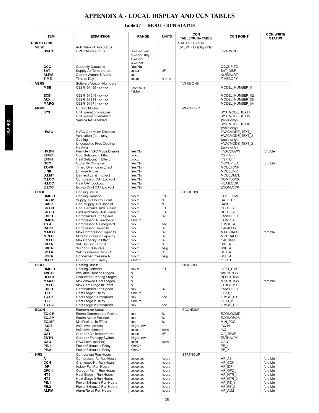
Table 27 — MODE - RUN STATUS

ITEM

EXPANSION

RANGE

UNITS

CCN

CCN POINT

CCN WRITE

TABLE/SUB---TABLE

STATUS


RUN STATUS


STATUS DISPLAY


VIEW

Auto View of Run Status


(VIEW = Display only)


HVAC

HVAC Mode Status

1=Disabled


HVACMODE


2=Fan Only


3=Cool


OCC


4=Heat


Currently Occupied

Yes/No


OCCUPIED


SAT

Supply Air Temperature

xxx..x

dF


SAT_DISP


ALRM

Current Alarms & Alerts

xx


ALRMALRT


TIME

Time of Day

xx.xx

hh.mm


TIMECOPY


VERS

Software Version Numbers


VERSIONS


MBB

CESR131459---xx---xx

(xx---xx in


MODEL_NUMBER_01


ECB

CESR131249---xx---xx

table)


MODEL_NUMBER_02


AUX

CESR131333---xx---xx


MODEL_NUMBER_03


MARQ

CESR131171---xx---xx


MODEL_NUMBER_04


MODE

Control Modes


MODEDISP


SYS

Unit operation disabled


SYS_MODE_TEXT1


Unit operation enabled


SYS_MODE_TEXT2


Service test enabled


(table only)


SYS_MODE_TEXT3


HVAC


(table only)


HVAC Operation Disabled


HVACMODE_TEXT_1


Ventilation (fan---only)


HVACMODE_TEXT_2


Cooling


(table only)


Unoccupied Free Cooling


HVACMODE_TEXT_3


HV.DN

Heating


(table only)


Remote HVAC Mode Disable

Yes/No


HVACDOWN

forcible

EFF.C

Cool Setpoint in Effect

xxx.x


CSP_EFF


EFF.H

Heat Setpoint in Effect

xxx.x


HSP_EFF


OCC

Currently Occupied

Yes/No


OCCUPIED

forcible

T.OVR

Timed Override in Effect

Yes/No


MODETOVR


LINK

Linkage Active

Yes/No


MODELINK


D.LMT

Demand Limit In Effect

Yes/No


MODEDMDL


C.LOC

Compressor OAT Lockout

Yes/No


COMPLOCK


H.LOC

Heat OAT Lockout

Yes/No


HEATLOCK


E.LOC

Econo Cool OAT Lockout

Yes/No


ECONLOCK


COOL

Cooling Status


COOLDISP


DMD.C

Cooling Demand

xxx.x

^F


COOL_DMD


SA.CP

Supply Air Control Point

xxx.x

dF


SA_CTLPT


SASP

Cool Supply Air Setpoint

xxx.x

dF


SASP


SR.CD

Cool Demand SASP Reset

xxx.x

^F


CD_RESET


SR.RH

Dehumidifying SASP Reset

xxx.x

^F


RH_RESET


F.SPD

Commanded Fan Speed

xxx

%


FANSPEED


CMP.A

Compressor A Feedback

On/Off


COMP_A


TG.A

Compressor A Timeguard

xxx

sec


TIMGD_A


CAPC

Compressor Capacity

xxx

%


CAPACITY


MAX.C

Max Compressor Capacity

xxx

%


MAX_CAPC

forcible

MIN.C

Min Compressor Capacity

xxx

%


MIN_CAPC


LMT.C

Max Capacity In Effect

xxx

%


CAPLIMIT


SST.A

Sat. Suction Temp A

xxx.x

dF


SST_A


SSP.A

Suction Pressure A

xxx.x

psig


SSP_A


SCT.A

Sat. Condenser Temp A

xxx.x

dF


SCT_A


SCP.A

Condenser Pressure A

xxx.x

psig


SCP_A


OFC.1

Outdoor Fan 1 Relay

On/Off


OFC_1


HEAT

Heating Status


HEATDISP


DMD.H

Heating Demand

xxx.x

^F


HEAT_DMD


AVL.H

Available Heating Stages

x


AVLHSTGS


REQ.H

Requested Heating Stages

x


REQHSTGS


MAX.H

Max Allowed Heat Stages

x


MAXHSTGS

forcible

LMT.H

Max Heat Stage In Effect

x


HSTGLIMT


F.SPD

Commanded Fan Speed

xxx

%


FANSPEED


HT.1

Heat Stage 1 Relay

On/Off


HEAT_1


TG.H1

Heat Stage 1 Timequard

xxx

sec


TIMGD_H1


HT.2

Heat Stage 2 Relay

On/Off


HEAT_2


TG.H2

Heat Stage 2 Timequard

xxx

sec


TIMGD_H2


ECON

Economizer Status


ECONDISP


EC.CP

Econo Commanded Position

xxx

%


ECONOCMD


EC.AP

Econo Actual Position

xxx

%


ECONOPOS


EC.MP

Min Position in Effect

xxx

%


MIN_POS


IAQ.S

IAQ Level (switch)

High/Low


IAQIN


IAQ

IAQ Level (sensor)

xxxx

ppm


IAQ


OAT

Outdoor Air Temperature

xxx.x

dF


OA_TEMP


ENTH

Outdoor Enthalpy Switch

High/Low


ENTHALPY


OAQ

OAQ Level (sensor)

xxxx

ppm


OAQ


PE.1

Power Exhaust 1 Relay

On/Off


PE_1


PE.2

Power Exhaust 2 Relay

On/Off


PE_2


HRS

Component Run Hours


STRTHOUR


A1

Compressor A1 Run Hours

xxxxx.xx

hours


HR_A1

forcible

CCH

Crankcase Htr Run Hours

xxxxx.xx

hours


HR_CCH

forcible

IDF

Indoor Fan Run Hours

xxxxx.xx

hours


HR_IDF

forcible

OFC.1

Outdoor Fan 1 Run Hours

xxxxx.xx

hours


HR_OFC_1

forcible

HT.1

Heat Stage 1 Run Hours

xxxxx.xx

hours


HR_HTR_1

forcible

HT.2

Heat Stage 2 Run Hours

xxxxx.xx

hours


HR_HTR_2

forcible

PE.1

Power Exhaust1 Run Hours

xxxxx.xx

hours


HR_PE_1

forcible

PE.2

Power Exhaust2 Run Hours

xxxxx.xx

hours


HR_PE_2

forcible

ALRM

Alarm Relay Run Hours

xxxxx.xx

hours


HR_ALM

forcible

68

Page 68
Image 68
Carrier 48/50PD05 manual Appendix a Local Display and CCN Tables, Mode RUN Status

48/50PD05 specifications

The Carrier 48/50PD05 is a remarkable addition to Carrier's lineup of rooftop units, offering advanced cooling and heating solutions for commercial applications. Designed for medium-sized buildings, this unit is well-suited for both new installations and as a replacement for older systems, thanks to its versatile features and efficient performance.

One of the standout features of the 48/50PD05 is its energy efficiency. It incorporates state-of-the-art technology to achieve high Seasonal Energy Efficiency Ratios (SEER) and EER ratings, reducing operational costs while delivering superior comfort. The unit is also compliant with the latest energy regulations, making it an environmentally friendly choice for building owners concerned about sustainability.

The 48/50PD05 is equipped with a highly efficient scroll compressor, which not only enhances performance but also contributes to quiet operation. This is a significant advantage in commercial spaces where noise levels need to be kept in check for comfort and productivity. Additionally, the unit includes advanced airflow design, ensuring even distribution of conditioned air throughout the space.

Technologically, the Carrier 48/50PD05 features Carrier's Infinity Control system, which allows for precise control of indoor climate. This intelligent control mechanism can be integrated with smart building management systems, enabling users to monitor and manage energy use effectively. Wi-Fi connectivity is also available, providing remote access for real-time adjustments and diagnostics.

Durability is another characteristic of the 48/50PD05. Constructed with high-quality materials, the unit withstands various environmental conditions, ensuring longevity and reliability. Moreover, the modular design facilitates easy maintenance, making service procedures efficient and cost-effective.

In addition to cooling, the Carrier 48/50PD05 offers heating capabilities, often utilizing gas or electric heating options that can be tailored to the specific needs of a building. The unit can also be equipped with integrated economizers, allowing for free cooling during suitable outdoor conditions, further enhancing energy savings.

Overall, the Carrier 48/50PD05 stands out as a high-performance HVAC solution that combines efficiency, technology, and durability. It provides building owners with a versatile tool to ensure comfort while minimizing their environmental footprint. With a strong emphasis on energy savings and advanced control features, this rooftop unit is a smart investment for any commercial property.