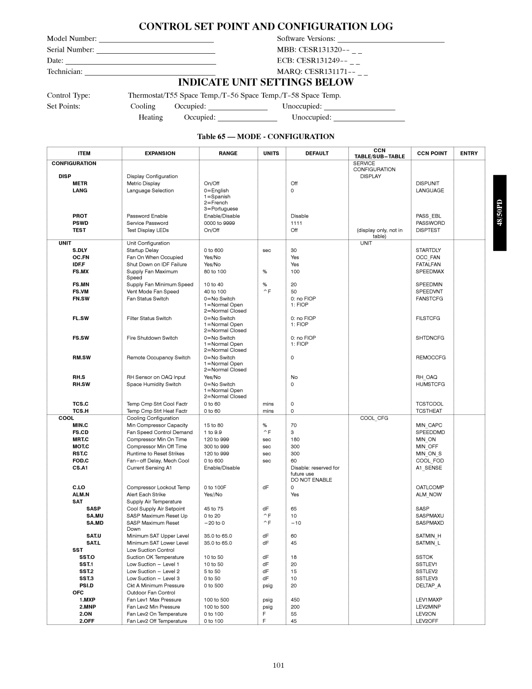
Carrier 48/50PD05 manual Control Set Point And Configuration Log, Indicate Unit Settings Below

Models: 48/50PD05

1 106
Download 106 pages 12.23 Kb
Page 101
Image 101
CONTROL SET POINT AND CONFIGURATION LOG

CONTROL SET POINT AND CONFIGURATION LOG

Model Number: _____________________________

Software Versions: ___________________________

Serial Number: ______________________________

MBB: CESR131320-- _ _

Date: ______________________________________

ECB: CESR131249-- _ _

Technician: _________________________________

MARQ: CESR131171-- _ _

INDICATE UNIT SETTINGS BELOW

Control Type:

Thermostat/T55 Space Temp./T-56 Space Temp./T-58 Space Temp.


Set Points:

Cooling

Occupied: _______________

Unoccupied: __________________


Heating

Occupied: _______________


Unoccupied: __________________


Table 65 — MODE - CONFIGURATION


ITEM

EXPANSION


RANGE

UNITS


DEFAULT

CCN

CCN POINT

ENTRY


TABLE/SUB---TABLE


CONFIGURATION


SERVICE


CONFIGURATION


DISP

Display Configuration


DISPLAY


METR

Metric Display


On/Off


Off


DISPUNIT


LANG

Language Selection


0=English


0


LANGUAGE


1=Spanish


2=French


3=Portuguese


PROT

Password Enable


Enable/Disable


Disable


PASS_EBL


PSWD

Service Password


0000 to 9999


1111


PASSWORD


TEST

Test Display LEDs


On/Off


Off

(display only, not in

DISPTEST


table)


UNIT

Unit Configuration


UNIT


S.DLY

Startup Delay


0 to 600

sec


30


STARTDLY


OC.FN

Fan On When Occupied


Yes/No


Yes


OCC_FAN


IDF.F

Shut Down on IDF Failure


Yes/No


Yes


FATALFAN


FS.MX

Supply Fan Maximum


80 to 100

%


100


SPEEDMAX


Speed


FS.MN

Supply Fan Minimum Speed


10 to 40

%


20


SPEEDMIN


FS.VM

Vent Mode Fan Speed


40 to 100

^F


50


SPEEDVNT


FN.SW

Fan Status Switch


0=No Switch


0: no FIOP


FANSTCFG


1=Normal Open


1: FIOP


2=Normal Closed


FL.SW

Filter Status Switch


0=No Switch


0: no FIOP


FILSTCFG


1=Normal Open


1: FIOP


2=Normal Closed


FS.SW

Fire Shutdown Switch


0=No Switch


0: no FIOP


SHTDNCFG


1=Normal Open


1: FIOP


2=Normal Closed


RM.SW

Remote Occupancy Switch


0=No Switch


0


REMOCCFG


1=Normal Open


2=Normal Closed


RH.S

RH Sensor on OAQ Input


Yes/No


No


RH_OAQ


RH.SW

Space Humidity Switch


0=No Switch


0


HUMSTCFG


1=Normal Open


2=Normal Closed


TCS.C

Temp Cmp Strt Cool Factr


0 to 60

mins


0


TCSTCOOL


TCS.H

Temp Cmp Strt Heat Factr


0 to 60

mins


0


TCSTHEAT


COOL

Cooling Configuration


COOL_CFG


MIN.C

Min Compressor Capacity


15 to 80

%


70


MIN_CAPC


FS.CD

Fan Speed Control Demand


1 to 9.9

^F


3


SPEEDDMD


MRT.C

Compressor Min On Time


120 to 999

sec


180


MIN_ON


MOT.C

Compressor Min Off Time


300 to 999

sec


300


MIN_OFF


RST.C

Runtime to Reset Strikes


120 to 999

sec


300


MIN_ON_S


FOD.C

Fan---off Delay, Mech Cool


0 to 600

sec


60


COOL_FOD


CS.A1

Current Sensing A1


Enable/Disable


Disable: reserved for


A1_SENSE


future use


DO NOT ENABLE


C.LO

Compressor Lockout Temp


0 to 100F

dF


0


OATLCOMP


ALM.N

Alert Each Strike


Yes//No


Yes


ALM_NOW


SAT

Supply Air Temperature


SASP

Cool Supply Air Setpoint


45 to 75

dF


65


SASP


SA.MU

SASP Maximum Reset Up


0 to 20

^F


10


SASPMAXU


SA.MD

SASP Maximum Reset


---20 to 0

^F


---10


SASPMAXD


Down


SAT.U

Minimum SAT Upper Level


35.0 to 65.0

dF


60


SATMIN_H


SAT.L

Minimum SAT Lower Level


35.0 to 65.0

dF


45


SATMIN_L


SST

Low Suction Control


SST.O

Suction OK Temperature


10 to 50

dF


18


SSTOK


SST.1

Low Suction --- Level 1


10 to 50

dF


20


SSTLEV1


SST.2

Low Suction --- Level 2


5 to 50

dF


15


SSTLEV2


SST.3

Low Suction --- Level 3


0 to 50

dF


10


SSTLEV3


PSI.D

Ckt A Minimum Pressure


0 to 500

psig


20


DELTAP_A


OFC

Outdoor Fan Control


1.MXP

Fan Lev1 Max Pressure


100 to 500

psig


450


LEV1MAXP


2.MNP

Fan Lev2 Min Pressure


100 to 500

psig


200


LEV2MINP


2.ON

Fan Lev2 On Temperature


0 to 100

F


55


LEV2ON


2.OFF

Fan Lev2 Off Temperature


0 to 100

F


45


LEV2OFF


48/50PD

101

Page 101
Image 101
Carrier 48/50PD05 manual Control Set Point And Configuration Log, Indicate Unit Settings Below, Mode - Configuration