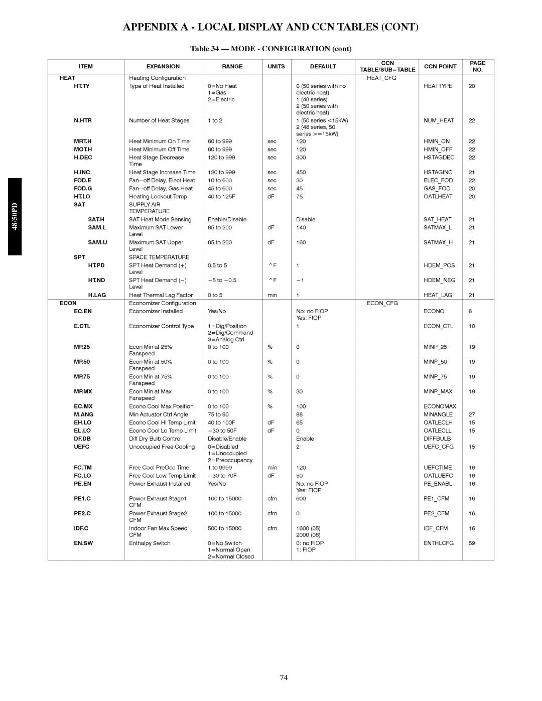
48/50PD05 specifications
The Carrier 48/50PD05 is a remarkable addition to Carrier's lineup of rooftop units, offering advanced cooling and heating solutions for commercial applications. Designed for medium-sized buildings, this unit is well-suited for both new installations and as a replacement for older systems, thanks to its versatile features and efficient performance.One of the standout features of the 48/50PD05 is its energy efficiency. It incorporates state-of-the-art technology to achieve high Seasonal Energy Efficiency Ratios (SEER) and EER ratings, reducing operational costs while delivering superior comfort. The unit is also compliant with the latest energy regulations, making it an environmentally friendly choice for building owners concerned about sustainability.
The 48/50PD05 is equipped with a highly efficient scroll compressor, which not only enhances performance but also contributes to quiet operation. This is a significant advantage in commercial spaces where noise levels need to be kept in check for comfort and productivity. Additionally, the unit includes advanced airflow design, ensuring even distribution of conditioned air throughout the space.
Technologically, the Carrier 48/50PD05 features Carrier's Infinity Control system, which allows for precise control of indoor climate. This intelligent control mechanism can be integrated with smart building management systems, enabling users to monitor and manage energy use effectively. Wi-Fi connectivity is also available, providing remote access for real-time adjustments and diagnostics.
Durability is another characteristic of the 48/50PD05. Constructed with high-quality materials, the unit withstands various environmental conditions, ensuring longevity and reliability. Moreover, the modular design facilitates easy maintenance, making service procedures efficient and cost-effective.
In addition to cooling, the Carrier 48/50PD05 offers heating capabilities, often utilizing gas or electric heating options that can be tailored to the specific needs of a building. The unit can also be equipped with integrated economizers, allowing for free cooling during suitable outdoor conditions, further enhancing energy savings.
Overall, the Carrier 48/50PD05 stands out as a high-performance HVAC solution that combines efficiency, technology, and durability. It provides building owners with a versatile tool to ensure comfort while minimizing their environmental footprint. With a strong emphasis on energy savings and advanced control features, this rooftop unit is a smart investment for any commercial property.
