122
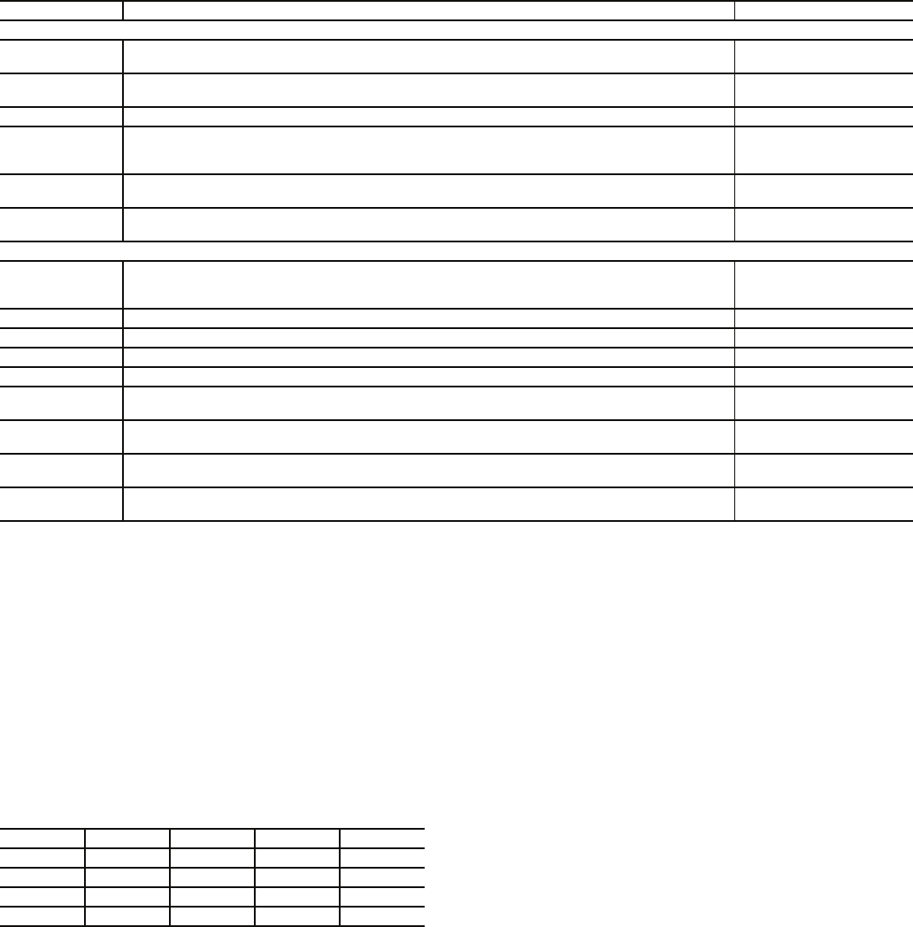
Table 95 — Thermistors and Unit Operation Control Pressure Transducers
LEGEND
FAN STATUS SWITCH — The units can be equipped with
an optional fan status switch that will monitor the pressure rise
across the indoor fans.
RETURN AIR CO2 SENSOR — The unit can be equipped
with a return air IAQ CO2 sensor that is used for the demand
control ventilation. The sensor is located in the return air sec-
tion and can be accessed from the filter access door.
BOARD ADDRESSES — Each board in the system has an
address. The MBB has a default address of 1 but it does have
an instance jumper that should be set to 1 as shown in Fig. 26.
For the other boards in the system there is a 4-dip switch head-
er on each board that should be set as shown below.
0 = On; 1 = Off
Accessory Control Components — In addition to
the factory-installed options, the units can also be equipped
with several field-installed accessories that expand the control
features of the unit. The following hardware components can
be used as accessories.
ROOM THERMOSTATS — The ComfortLink™ controls
support a conventional electro-mechanical or electronic ther-
mostat that uses the Y1, Y2, W1, W2, and G signals. The
control also supports an additional input for an occupied/
unoccupied command that is available on some new thermo-
stats. The ComfortLink controls can be configured to run with
up to 6 stages of capacity. Although the unit can be configured
for normal 2-stage control, it is recommended that the multi-
stage control be used. The room thermostat is connected to
TB202.
The ComfortLink controls also support the use of space
temperature sensors and can be used with the T55 and T56
sensors. The controls can also be used with CCN communicat-
ing T58 room sensor. The T55 and T56 sensors are connected
to TB202 terminals 8, 9, and 10. The T58 sensor is connected
to the CCN connections on COMM board. Whenever a unit
equipped with heat is operated without a thermostat, the user
must install the red jumpers from R to W1, and W2 on TB202
for the heat function to work correctly.
SPACE CO2 SENSORS — The ComfortLink controls also
support a CO2 IAQ sensor that can be located in the space for
use in demand ventilation. The sensor must be a 4 to 20 mA
sensor and should be connected to TB202 terminals 11 and 12.
ECONOMIZER HUMIDITY CHANGEOVER SEN-
SORS — The ComfortLink controls support 5 different
changeover systems for the economizer. These are:
• Outdoor enthalpy switch
• Outdoor air dry bulb
• Differential dry bulb
• Outdoor air enthalpy curves
• Differential enthalpy
• Custom curves (a combination of an enthalpy/dewpoint
curve and a dry bulb curve).
The units are equipped as standard with an outdoor air
enthalpy control. Outside air and return air dry bulb sensors
which support the dry bulb changeover method are also
supplied as standard. If the other methods are to be used, then a
field-installed humidity sensor must be installed for outdoor air
enthalpy and customer curve control and two humidity sensors
must be installed for differential enthalpy. Installation holes are
pre-drilled and wire harnesses are installed in every unit for
connection of the humidity sensors. The ComfortLink controls
have the capability to convert the measured humidity and
dry bulb temperature into enthalpy.
SENSOR DESCRIPTION AND LOCATION PART NO.
Thermistors
CCT Cooling Coil Thermistor input. Provided with factory-option hydronic heat. Located on face of the
hydronic heating coil. Consists of 4 thermistors wired into a 2x2 array.
HH79NZ039 (4)
LST Limit Switch Thermistor. Provided with Staged Gas Control option. Located in the heating
compartment.
HH79NZ034
OAT Outside Air Thermistor. Located in top of the return plenum, attached to roof pole. HH79NZ039
RAT
Return Air Thermistor.
Without Economizer: Located on left side base rail in the return plenum.
With Economizer: Located on left side face of return damper section in the return plenum.
HH79NZ039
SAT Supply Air Thermistor. Located in the Supply Fan section, on left side of the fan housing.
(May be relocated or replaced when unit is used with CCN Linkage systems; see page 60.)
HH79NZ039
LAT 1,2,3 Leaving Air Thermistors, provided with Staged Gas Control option. Shipped in the heating
compartment. Installer must pull out and mount in the supply duct.
HH79NZ034 (3)
Control Pressure Transducers
BP
Building Pressure. Provided with Modulating Power Exhaust, High-Capacity Power Exhaust
and Return Fan options. Located in the auxiliary control box (left-hand side of unit near return
plenum).
HK05ZG018
DPA Discharge Pressure (refrigerant), Circuit A. Located on compressor A1 high-side connections. HK05YZ007
DPB Discharge Pressure (refrigerant), Circuit B. Located on compressor B1 high-side connections. HK05YZ007
SPA Suction Pressure (refrigerant), Circuit A. Located on compressor A1 low-side connections. HK05YZ001
SPB Suction Pressure (refrigerant), Circuit B. Located on compressor B1 low-side connections. HK05YZ001
DSP Duct Static Pressure. Provided with VAV models equipped with VFD or Inlet Guide Vane options.
Located in the auxiliary control box (right-hand side of unit near return plenum).
HK05ZG010
FT_SF Supply Air Cfm (velocity pressure). Provided with factory-option return fan system
(sizes 075-105 only). Located in the supply fan compartment, on right side, on vertical post.
HK05ZG015
FT_RF Return Air Cfm (velocity pressure). Provided with factory-option return fan system
(sizes 075-105 only). Located in auxiliary control box (right-hand side, filter access panel).
HK05ZG07
Outside Air CFM
Control
Outside Air Cfm Monitor (velocity pressure). Provided with the Outside Air Cfm Control option.
Located in auxiliary control box (right-hand side, filter access panel).
50ZZ400290 (030-070)
50ZZ400289 (075-105)
VAV — Variable Air Volume
BOARD SW1 SW2 SW3 SW4
RCB0000
ECB1000
SCB0000
CEM0000