BROADway
Page
FCC Requirements, Part
Safety of Information Technology Equipment
Compliance
Card Service Framing Coding
Network
Type
Jack
Industry Canada ICES-003
Industry Canada CS-03
English
French
Safety Information
Electrostatic Discharge ESD Precautions
Warranty Product Returns
Warranty
Limitation of Warranty & Limitation of Remedies
Third-Party Software Notices
Sun Microsystems, Inc., Software Notice
Preface
Table of Contents
Configuration
Table of Contents
Ports and Cables
Index
Xiv BROADway Release
Chapter
Overview
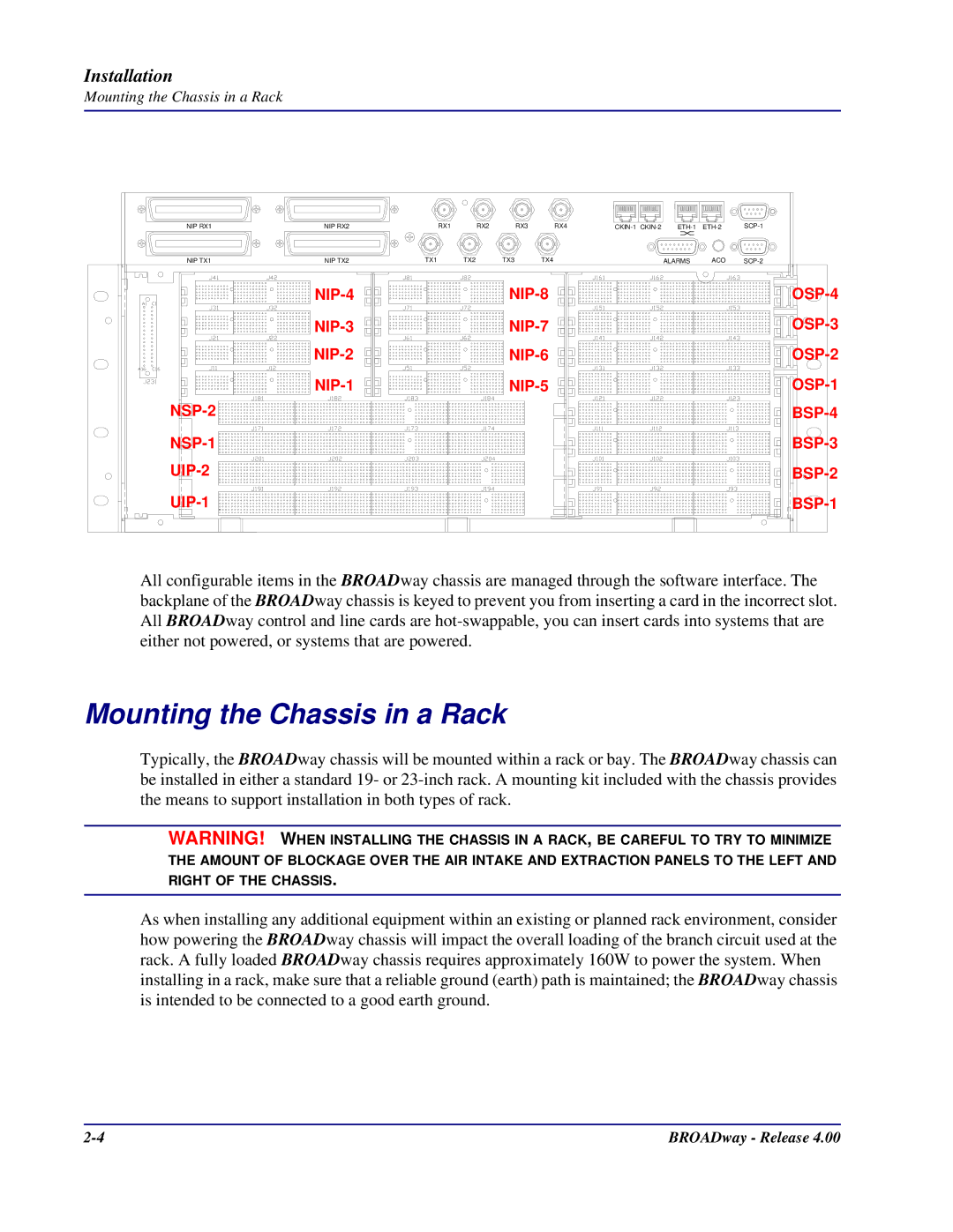
Installation
Chassis Overview
Top I/O Panel Front View of the Bits Chassis
Top I/O Panel Front View of the ITU Chassis
Mounting the Chassis in a Rack
Mounting the Chassis in a Rack
Side View of the Chassis
Cabling Power and Ground
Extension Plate
Connect to +24VDC or -48VDC power source
Ground at power source 48 VDC
BROADway Chassis Rear Panel View
Connect to Earth ground
+24 VDC Ground at power source
+24 VDC Feed
Cabling the Serial Craft Port
Cabling the Ethernet Port
Connect to the serial port of a PC
Connect an Ethernet cable from a PC to ETH-1
Connect a second clock source Connect a clock source
Cabling the Network Synchronization Port
Cabling the Clock Ports on the Bits Chassis
Cabling the Alarm Ports
Cabling the Clock Ports on the ITU Chassis
Alarm Input Sensing
Pin Name
Installing the NSP101 Control Card
Alarm Output Reporting
Alarm Cut Off ACO
Insert one or two NSP101 cards
Module Red LED Module Green LED Status Top Bottom
Active Green LED Status
ETH Yellow LED Status Top #1 Bottom
Alarm SUM Red LED Status
PWR Red LED #2 PWR Red LED #1 Status Top Bottom
Installing the NIP400 Line Interface Card
Insert NIP400 cards optional
Connect to DSX panels or punch down blocks
Cabling the NIP400
Clip
NIP400 LED Indicators
Port LED Port State
Grommets Insert NHP160 cards optional
Installing the NHP160 Line Interface Card
Cabling and Inserting the NHP160 Line Interface Card
NHP160 LED Indicators
A y
Installing the BSP200 Line Interface Card
BSP200 line terminations
Connect BNC coaxial cables
BSP200 LED Indicators
Cabling the BSP200
Interface Red LED Interface Green Status Bottom LED Top
Grommets
Installing OSP155/ESP155/BCP155 Line Interface Cards
Insert OSP155, ESP155, or BCP155 cards optional
Cabling the OSP155 and BCP155
Installation
OSP155, BCP155, and ESP155 LED Indicators
Cabling the ESP155
Attaching the Front Panel
Applying Power to the Chassis
W a y
Installing New Cards
Maintaining BROADway Hardware
Installing Additional OSP155, ESP155 or BCP155 Cards
Replacing Failed Cards
Maintaining the Fan Tray
Fan Board
Configuration
Configuration
Default BROADway IP Address
Assigning an IP Address to the BROADway System
Assigning a Different IP Address
ACT-USERNSP1234CUSTOMER,BROADWAY
PS#configure
PS#configure PSNSP-config#no interface bvi
PS#show BVI status bridge-group number
PS#show bvi status
Management Access to the BROADway System
Viewing Serial Craft Port Settings With the GUI
Local SCP-1 Serial Craft Port Access
Remote Modem SCP-1 Serial Craft Port Access
Ethernet Port Command Line Access
Ethernet Port Web Browser GUI Access
Logging In With the Web Browser Interface GUI
Enter
Configuration
Configuration
Click here to minimize this window
This window must remain running in the background
Logging In With the Command Line Interface CLI
ACT-USERNSP1234username,password
ACT-USERNSP1234
CANC-USERNSP1234
Setting Up User Accounts
User Account Management Using the GUI
User Account Management Using TL1
RTRV-USERNSP1234ALL
RTRV-USERNSP1234ACTIVE
RTRV-USERNSP1234ME
ENT-USERNSP1234joetech,mypassword,ADMIN,TL1
DLT-USERNSP1234username
Changing Your Password
Changing Your Password Using the GUI
Changing Your Password Using TL1
Current Password field, type your current password
Setting the System Date and Time
Setting the Date and Time Using the GUI
Setting the Date and Time Using TL1
ED-DATNSP1234YY-MM-DD,HH-MM-SS
Setting System Node Parameters
Setting System Node Parameters Using the GUI
Setting System Node Parameters Using TL1
RTRV-UDATANSP1234
Examples
ED-UDATANSP1234US
ED-EQPTNSP1234DIS
RTRV-EQPTNSP-x.PWR-11234
ED-EQPTNSP1234ENA
Managing the BROADway Configuration Database
Managing the Database Using the GUI
Managing the Database Using TL1
RTRV-DBNSP1
CPY-DBNSP1RUNNING,SAVED,newdbname
CPY-DBNSP1SAVED,offlinename
Exporting the BROADway Database to a TL1 Script
Re-Starting the BROADway System Using TL1
Copying Files Between NSP101 Controllers
Using FTP with the BROADway System
INIT-SYSNSP1234ALL
NSP1 rtrv-sw-vernsp1234all
Upgrading System Software
Rtrv-sw-vernsp1234all
Ftp put c\temp\bw308.zip
\ftp
Ftp cd /FLASH
NSP1 set-upgradensp1234bw308,all
Set-upgrade command NSP1 set-upgradensp1234bw308
Rolling Back a Software Update
Upgrading the Boot ROM
NSP1 exec-sysnsp1234bootUpdate
NSP1 init-sysnsp1234FORCE
TL1 Software Upgrade Commands
RTRV-SW-VERNSP1234ALL
Appendix a
SCP-1 and SCP-2 Connector Pinouts
SCP-1 SCP-2 future use Pin Signal Name
ETH-1 and ETH-2 Connector Pinouts
ETH-1 ETH-2 Pin Signal
CKIN-1 and CKIN-2 Connector Pinouts Bits Only
Pin Signal
NIP400 Connector Pinouts NIP TX1-RX1, NIP TX2-RX2
T1/E1 NIP400 TX tip TX ring RX tip RX ring Circuit Card
Ports and Cables
Alarms Connector Pinouts
Pin Color Name Signal
NHP160 Connector Pinouts
Scsi Pin Color Signal
Ports and Cables
Ports and Cables
Index
Index
BROADway Release Index
Index