Parallel Interface
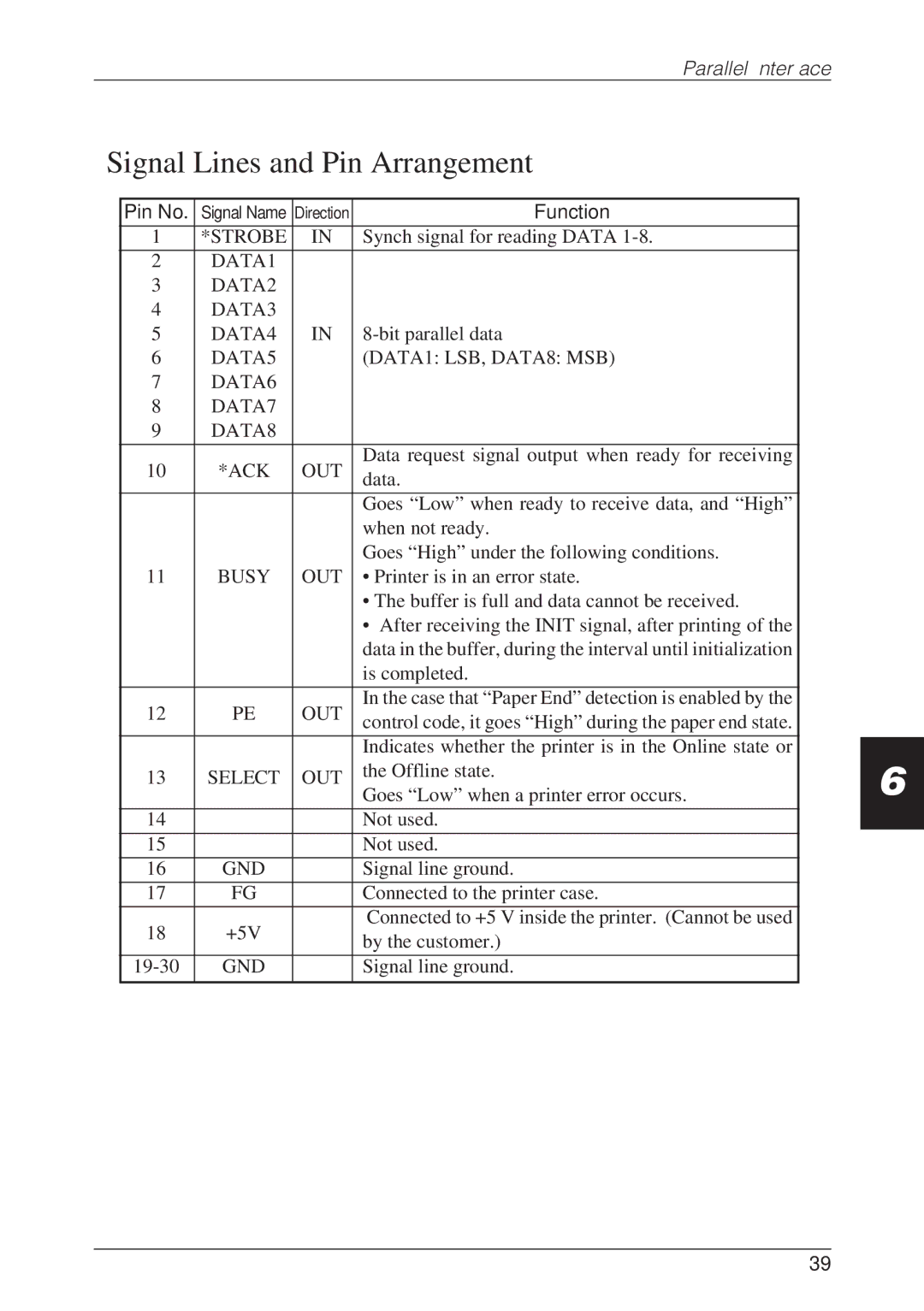
Signal Lines and Pin Arrangement
Pin No. | Signal Name | Direction | Function | |
1 | *STROBE | IN | Synch signal for reading DATA | |
2 | DATA1 |
|
| |
3 | DATA2 |
|
| |
4 | DATA3 |
|
| |
5 | DATA4 | IN | ||
6 | DATA5 |
| (DATA1: LSB, DATA8: MSB) | |
7 | DATA6 |
|
| |
8 | DATA7 |
|
| |
9 | DATA8 |
|
| |
10 | *ACK | OUT | Data request signal output when ready for receiving | |
data. | ||||
|
|
| ||
|
|
|
| |
|
|
| Goes “Low” when ready to receive data, and “High” | |
|
|
| when not ready. | |
|
|
| Goes “High” under the following conditions. | |
11 | BUSY | OUT | • Printer is in an error state. | |
|
|
| • The buffer is full and data cannot be received. | |
|
|
| • After receiving the INIT signal, after printing of the | |
|
|
| data in the buffer, during the interval until initialization | |
|
|
| is completed. | |
12 | PE | OUT | In the case that “Paper End” detection is enabled by the | |
control code, it goes “High” during the paper end state. | ||||
|
|
| ||
|
|
|
| |
|
|
| Indicates whether the printer is in the Online state or | |
13 | SELECT | OUT | the Offline state. | |
Goes “Low” when a printer error occurs. | ||||
|
|
| ||
|
|
|
| |
14 |
|
| Not used. | |
15 |
|
| Not used. | |
16 | GND |
| Signal line ground. | |
17 | FG |
| Connected to the printer case. | |
18 | +5V |
| Connected to +5 V inside the printer. (Cannot be used | |
| by the customer.) | |||
|
|
| ||
GND |
| Signal line ground. | ||
|
|
|
|
6
39
