Chapter 6 Interfaces
Connector Connection Diagram
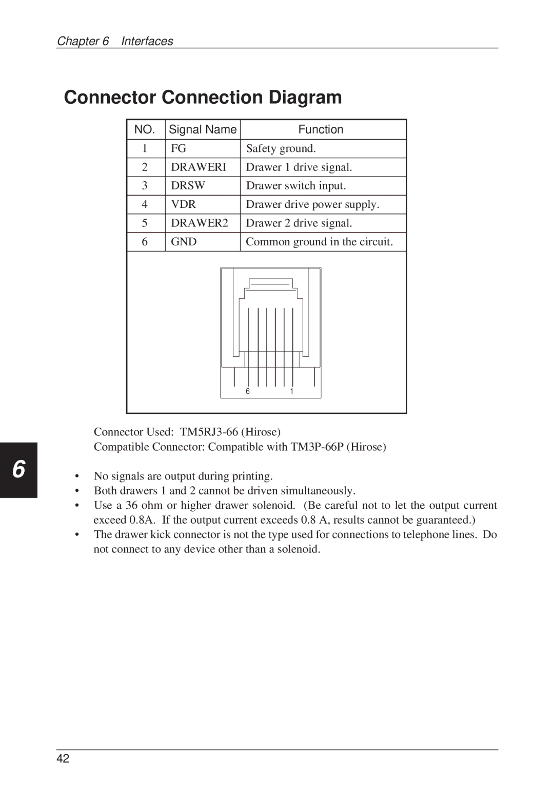
NO. | Signal Name |
|
|
|
|
|
|
|
|
|
|
| Function | ||||
|
|
|
|
|
|
|
|
|
|
|
|
|
|
|
|
|
|
1 | FG |
| Safety ground. | ||||||||||||||
|
|
|
|
|
|
|
|
|
|
|
|
|
|
|
|
|
|
2 | DRAWERI |
| Drawer 1 drive signal. | ||||||||||||||
|
|
|
|
|
|
|
|
|
|
|
|
|
|
|
|
|
|
3 | DRSW |
| Drawer switch input. | ||||||||||||||
|
|
|
|
|
|
|
|
|
|
|
|
|
|
|
|
|
|
4 | VDR |
| Drawer drive power supply. | ||||||||||||||
|
|
|
|
|
|
|
|
|
|
|
|
|
|
|
|
|
|
5 | DRAWER2 |
| Drawer 2 drive signal. | ||||||||||||||
|
|
|
|
|
|
|
|
|
|
|
|
|
|
|
|
|
|
6 | GND |
| Common ground in the circuit. | ||||||||||||||
|
|
|
|
|
|
|
|
|
|
|
|
|
|
|
|
|
|
|
|
|
|
|
|
|
|
|
|
|
|
|
|
|
|
|
|
|
|
|
|
|
|
|
|
|
|
|
|
|
|
|
|
|
|
|
|
|
|
|
|
|
|
|
|
|
|
|
|
|
|
|
|
|
|
|
|
|
|
|
|
|
|
|
|
|
|
|
|
|
|
|
|
|
|
|
|
|
|
|
|
|
|
|
|
|
|
|
|
|
|
|
|
|
|
|
|
|
|
|
|
|
|
|
|
|
|
|
|
|
|
|
|
|
|
|
|
|
|
|
|
|
|
|
|
|
|
|
|
|
|
|
|
|
|
|
|
|
|
|
|
|
|
|
|
|
|
|
|
|
|
|
|
|
|
|
|
|
|
|
|
|
|
|
|
|
|
|
|
|
|
|
|
|
|
|
|
|
|
6
61
Connector Used:
Compatible Connector: Compatible with
•No signals are output during printing.
•Both drawers 1 and 2 cannot be driven simultaneously.
•Use a 36 ohm or higher drawer solenoid. (Be careful not to let the output current exceed 0.8A. If the output current exceeds 0.8 A, results cannot be guaranteed.)
•The drawer kick connector is not the type used for connections to telephone lines. Do not connect to any device other than a solenoid.
42