Cisco Systems 11000 Series manual 14 illustrates the SFM front panel LEDs and connectors, 2-22

Models: 11000 Series

1 122
Download 122 pages 32.92 Kb
Page 70
Image 70
Figure 2-14illustrates the SFM front panel LEDs and connectors.

Chapter 2 Cabling the CSS

Cabling the CSS 11800 Modules
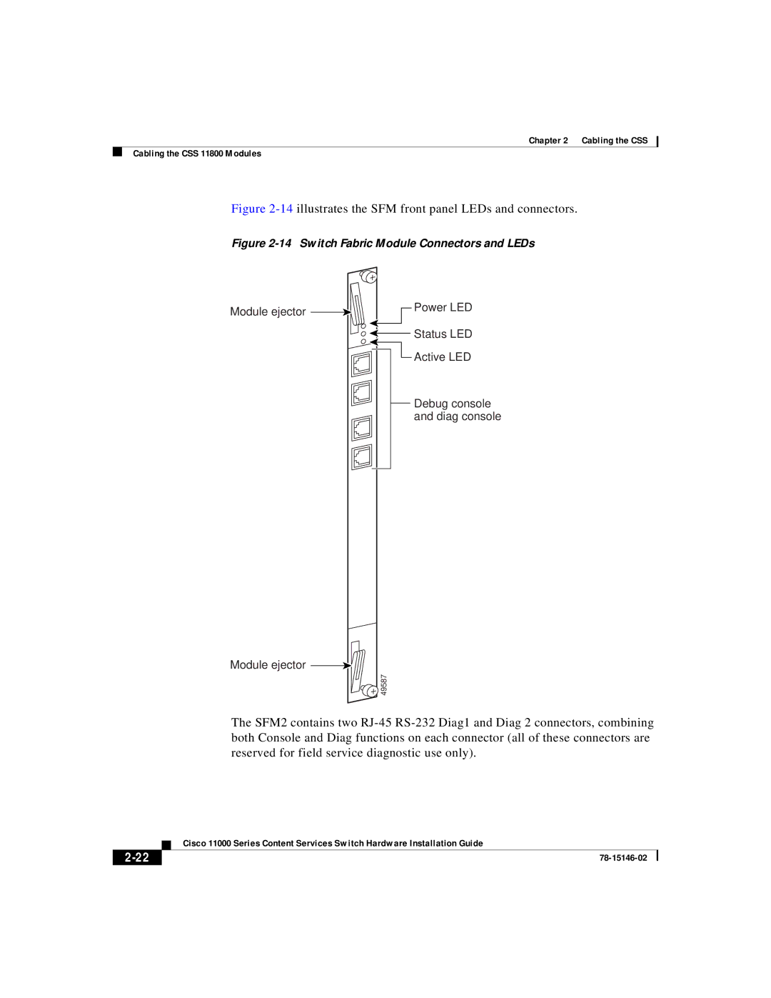
Figure 2-14illustrates the SFM front panel LEDs and connectors.

Figure 2-14 Switch Fabric Module Connectors and LEDs

Module ejector

Power LED


2-22 Status LED

Manual background Active LED

Debug console and diag console

Module ejector

Manual backgroundManual backgroundManual background49587

The SFM2 contains two RJ-45 RS-232 Diag1 and Diag 2 connectors, combining both Console and Diag functions on each connector (all of these connectors are reserved for field service diagnostic use only).


Cisco 11000 Series Content Services Switch Hardware Installation Guide

2-22

78-15146-02

Page 70
Image 70
Cisco Systems 11000 Series manual 14 illustrates the SFM front panel LEDs and connectors, 2-22