Chapter 1 Product Overview
Front Panel Description
Table | Cisco SFP+ Modules Supported for the | ||
|
|
|
|
Part Number |
| Description | |
|
|
| |
| 10 | ||
|
| meters | |
|
|
| |
| 10 | ||
|
| 5meters | |
|
|
|
|
For information about SFP modules, see your SFP module documentation and the “Installing SFP and SFP+ Modules” section on page
Note When ordering or using CX1 cables, ensure that the version identifier is 2 or higher.
The Catalyst
LEDs
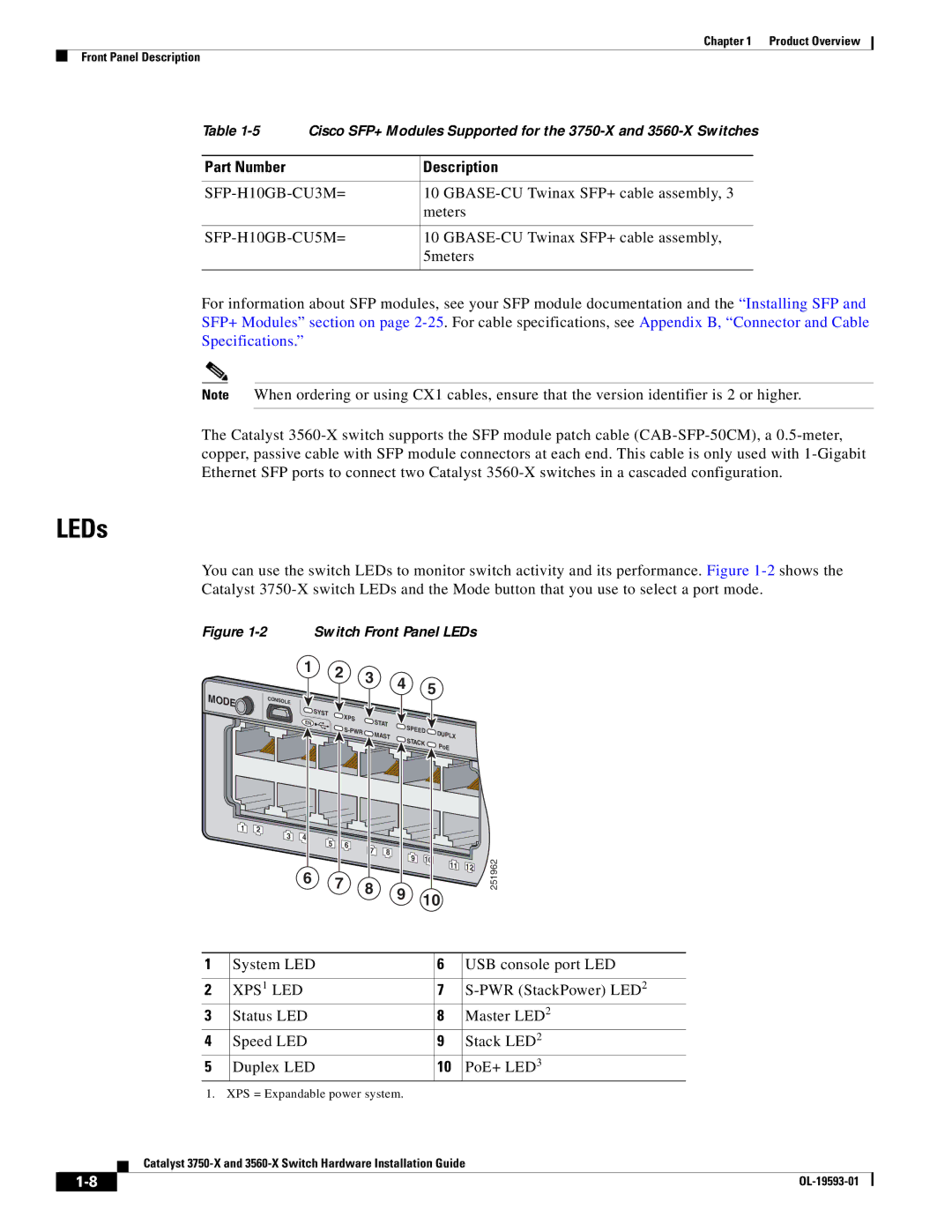
You can use the switch LEDs to monitor switch activity and its performance. Figure
Figure 1-2 Switch Front Panel LEDs
MODE![]()
1 | 2 |
1 2 3 4 5
CONSOLE
| S |
|
|
|
|
| YST | XPS |
|
|
|
EN |
| S |
|
| |
|
|
|
| ||
|
| S- | TAT | S |
|
|
| PWR | MAST | PEED | DUPLX |
|
|
| S | ||
|
|
|
| TACK | PoE |
|
|
|
|
|
3 | 4 | 6 |
|
|
|
|
| 5 | 8 |
|
|
| |
|
| 7 | 10 |
|
| |
|
|
| 9 | 11 | 12 | |
|
|
|
|
|
6 7 8 9 10
251962
1 | System LED | 6 | USB console port LED |
|
|
|
|
2 | XPS1 LED | 7 | |
3 | Status LED | 8 | Master LED2 |
4 | Speed LED | 9 | Stack LED2 |
5 | Duplex LED | 10 | PoE+ LED3 |
1. XPS = Expandable power system.
Catalyst
| ||
|