Appendix C Configuring the Switch with the
Accessing the CLI
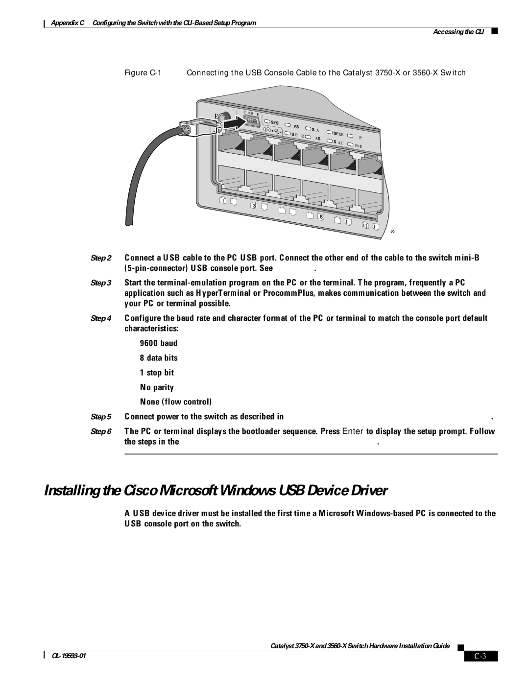
Figure C-1 Connecting the USB Console Cable to the Catalyst 3750-X or 3560-X Switch
MODE | CONS |
|
|
|
|
|
OLE |
|
|
|
|
| |
|
|
|
|
|
| |
|
| S |
|
|
|
|
|
| YST | XPS |
|
|
|
| EN |
| S |
|
| |
|
|
|
|
| ||
|
|
| S- | TAT | S |
|
|
|
|
| PEED |
| |
|
|
| PWR | MAST |
| DUPLX |
|
|
|
| S | ||
|
|
|
|
| TACK | PoE |
|
|
|
|
|
|
1 | 2 |
3 | 4 | 6 |
|
|
|
|
| 5 | 8 |
|
|
| |
|
| 7 | 10 |
|
| |
|
|
| 9 | 11 | 12 | |
|
|
|
|
|
253406
Step 2 Connect a USB cable to the PC USB port. Connect the other end of the cable to the switch
Step 3 Start the
Step 4 Configure the baud rate and character format of the PC or terminal to match the console port default characteristics:
•9600 baud
•8 data bits
•1 stop bit
•No parity
•None (flow control)
Step 5 Connect power to the switch as described in Chapter 3, “Power Supply and Fan Module Installation.”.
Step 6 The PC or terminal displays the bootloader sequence. Press Enter to display the setup prompt. Follow the steps in the “Configuring the Setup Program” section on page
Installing the Cisco Microsoft Windows USB Device Driver
A USB device driver must be installed the first time a Microsoft
•Installing the Cisco Microsoft Windows XP USB Driver
•Installing the Cisco Microsoft Windows 2000 USB Driver
•Installing the Cisco Microsoft Windows Vista and Windows 7 USB Driver
Catalyst
| ||
|
