Chapter 2 Switch Installation
Installing the Switch
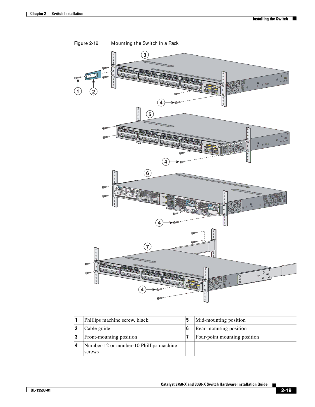
Figure
Mounting the Switch in a Rack
3
1 2
MODE |
|
|
|
|
|
SYST | XPS |
|
|
|
|
| STAT | SPEED |
| ||
| MAST | DUPLX | |||
|
| S | TACK | ||
|
|
|
| PoE | |
1 | 2 |
3 | 4 |
|
|
|
|
|
| 5 | 6 |
|
|
|
|
|
| 7 | 8 | 10 |
|
|
|
|
| 9 | 11 | 12 | |
|
|
|
|
|
13 | 14 |
|
|
|
|
|
|
|
|
|
| 15 | 16 | 17 | 18 |
|
|
|
|
|
|
|
|
| 19 | 20 |
|
|
|
| ||
|
|
|
|
|
|
| 21 | 22 | 23 | 24 |
25 | 26 |
|
|
|
|
|
|
|
|
|
| 27 | 28 | 29 | 30 |
|
|
|
|
|
|
|
|
|
|
| 31 | 32 | 33 | 34 |
|
|
|
|
|
|
|
|
|
|
| 35 | 36 |
37 | 38 |
|
|
|
|
|
|
|
|
|
| 39 | 40 | 41 | 42 |
|
|
|
|
|
|
|
|
|
|
| 43 | 44 | 45 | 46 |
|
|
|
|
|
|
|
| Catalyst 3 | 47 | 48 | ||
|
|
|
|
|
|
|
|
| ||
4
5
| C3KX- | NETWORK | |
|
|
| MODULE |
G1 | G2/TE1 |
|
|
| G3 | G4/TE2 | |
|
|
|
MODE |
| SYST |
|
|
|
|
|
|
|
|
| XPS | STAT | SPEED |
|
| |
|
|
| MAST | DUPLX |
| |||
|
|
|
| S | TACK |
| ||
|
|
|
|
|
| PoE |
| |
1 | 2 |
|
|
|
|
|
|
|
| 3 | 4 |
|
|
|
|
|
|
|
| 5 | 6 |
|
|
|
|
|
|
|
| 7 | 8 | 9 | 10 |
|
|
|
|
|
|
|
|
| 11 | 12 |
13 | 14 |
|
|
|
|
|
|
|
|
|
|
|
|
|
|
|
|
|
|
|
|
|
|
|
|
|
|
|
|
|
|
|
|
| 15 | 16 | 17 | 18 |
|
|
|
|
|
|
|
|
|
|
|
|
|
|
|
|
|
|
|
|
|
|
|
|
|
|
|
|
|
|
|
| 19 | 20 |
|
|
|
|
|
|
|
|
|
|
|
|
|
|
|
|
|
|
|
|
|
|
|
|
|
|
| ||
|
|
|
|
|
|
| 21 | 22 | 23 | 24 |
|
|
|
|
|
|
|
|
|
|
|
|
|
|
|
|
|
|
|
| C3KX- |
| NETWORK |
|
|
|
|
|
|
|
|
|
|
|
|
|
|
|
|
|
|
|
|
|
|
|
|
|
|
|
|
| |||||
|
|
|
|
|
|
|
|
|
| 25 | 26 |
| 29 | 30 |
|
|
|
|
|
|
|
|
|
|
|
|
|
|
|
|
| ||
|
|
|
|
|
|
|
|
|
|
| 27 | 28 |
|
|
|
|
|
|
|
|
|
|
|
|
|
|
|
|
|
| MODULE | ||
|
|
|
|
|
|
|
|
|
|
|
|
|
|
| 31 | 32 | 33 | 34 |
|
|
|
|
|
|
|
|
|
|
|
|
|
|
|
|
|
|
|
|
|
|
|
|
|
|
|
|
|
|
|
| 35 | 36 |
|
|
|
|
|
|
|
|
|
|
|
|
| ||
|
|
|
|
|
|
|
|
|
|
|
|
|
|
|
|
|
|
|
| 37 | 38 |
|
|
|
|
|
|
|
|
|
|
|
|
|
|
|
|
|
|
|
|
|
|
|
|
|
|
|
|
|
|
|
|
| 39 | 40 | 41 | 42 |
|
|
|
|
|
|
|
|
|
|
|
|
|
|
|
|
|
|
|
|
|
|
|
|
|
|
|
|
|
|
|
|
|
| 43 | 44 | 45 | 46 |
|
|
|
|
|
|
|
|
|
|
|
|
|
|
|
|
|
|
|
|
|
|
|
|
|
|
|
|
|
|
| Catalyst | 47 48 |
|
|
|
| ||
|
|
|
|
|
|
|
|
|
|
|
|
|
|
|
|
|
|
|
|
|
|
|
|
|
|
|
|
| PoE+48 | G1 | G2/TE1 |
|
|
|
|
|
|
|
|
|
|
|
|
|
|
|
|
|
|
|
|
|
|
|
|
|
|
|
|
|
|
|
|
| G3 | G4/TE2 | |
|
|
|
|
|
|
|
|
|
|
|
|
|
|
|
|
|
|
|
|
|
|
|
|
|
|
|
|
|
|
|
|
| |
CONSOLE |
|
| AUX |
STACK 1 | RESET |
| STACK 2 |
4
6
S- | AC |
|
|
|
PWR | OK |
|
| |
XPS |
|
|
| |
|
| PS OK | C3KX- |
|
|
|
|
| |
|
|
| AC OK |
|
|
| PS OK | C3KX- | |
|
|
|
|
4
7
MODE |
|
|
|
|
SYST | XPS |
|
|
|
| STAT | SPEED |
| |
| MAST | DUPLX | ||
|
| S | ||
|
|
| TACK | PoE |
4
|
| C3KX- | NETWORK | |
|
|
|
| MODULE |
Catalyst |
|
|
|
|
PoE+48 | G1 | G2/TE1 |
|
|
|
| G3 | G4/TE2 | |
|
|
|
|
1 | Phillips machine screw, black | 5 | |
|
|
|
|
2 | Cable guide | 6 | |
|
|
|
|
3 | 7 | ||
|
|
|
|
4 |
|
| |
| screws |
|
|
|
|
|
|
|
| Catalyst |
|
| |
|
|
| |||
|
|
|
| ||
|
|
|
| ||