Chapter 3 Power Supply and Fan Module Installation
Installation Guidelines
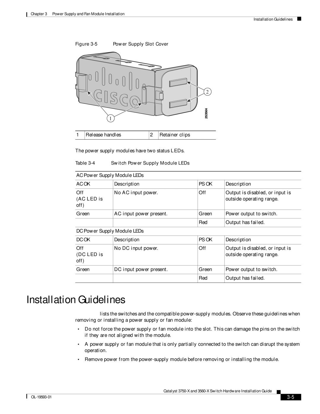
Figure 3-5 Power Supply Slot Cover
1
1
Release handles | 2 | Retainer clips |
|
|
|
2
253564
The power supply modules have two status LEDs.
Table | Switch Power Supply Module LEDs |
|
| |
|
|
| ||
AC Power Supply Module LEDs |
|
| ||
|
|
|
|
|
AC OK |
| Description | PS OK | Description |
|
|
|
|
|
Off |
| No AC input power. | Off | Output is disabled, or input is |
(AC LED is |
|
|
| outside operating range. |
off) |
|
|
|
|
|
|
|
|
|
Green |
| AC input power present. | Green | Power output to switch. |
|
|
|
|
|
|
|
| Red | Output has failed. |
|
|
|
| |
DC Power Supply Module LEDs |
|
| ||
|
|
|
|
|
DC OK |
| Description | PS OK | Description |
|
|
|
|
|
Off |
| No DC input power. | Off | Output is disabled, or input is |
(DC LED is |
|
|
| outside operating range. |
off) |
|
|
|
|
|
|
|
|
|
Green |
| DC input power present. | Green | Power output to switch. |
|
|
|
|
|
|
|
| Red | Output has failed. |
|
|
|
|
|
Installation Guidelines
Table
•Do not force the power supply or fan module into the slot. This can damage the pins on the switch if they are not aligned with the module.
•A power supply or fan module that is only partially connected to the switch can disrupt the system operation.
•Remove power from the
Catalyst
|
| ||
|
|