Chapter 1 Product Overview
Rear Panel Description
For information about replacing a power supply module, wiring a DC power supply module, and module specifications, see Chapter 3, “Power Supply and Fan Module Installation,” and Appendix A, “Technical Specifications.”
Fan Modules
The switch has two internal
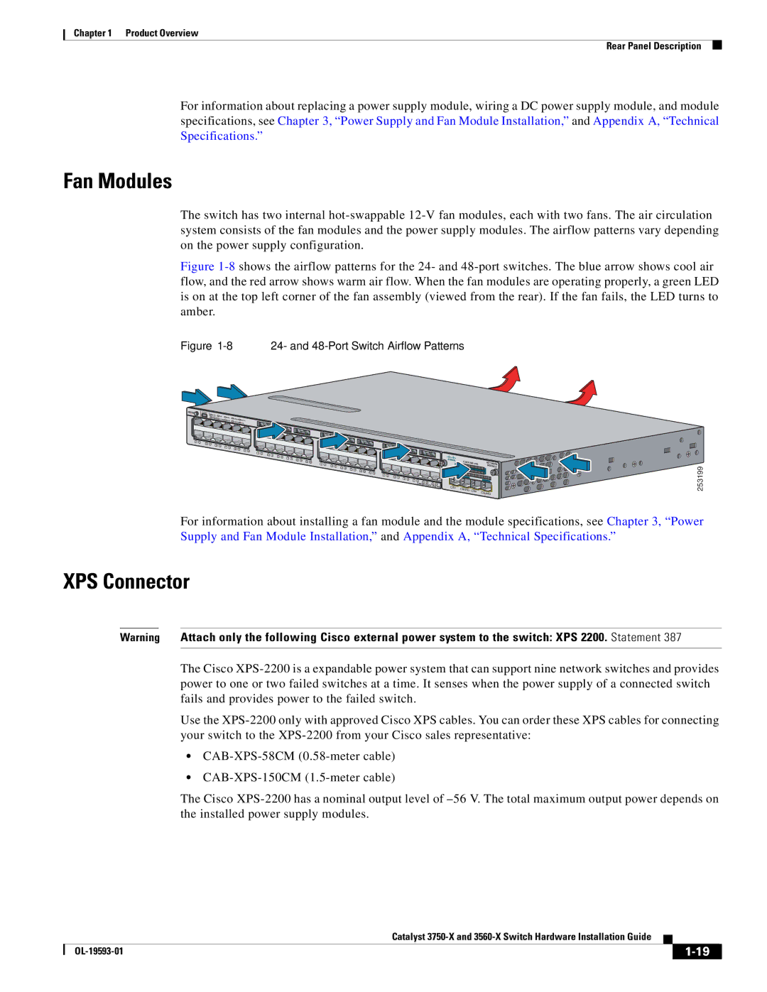
Figure 1-8 shows the airflow patterns for the 24- and 48-port switches. The blue arrow shows cool air flow, and the red arrow shows warm air flow. When the fan modules are operating properly, a green LED is on at the top left corner of the fan assembly (viewed from the rear). If the fan fails, the LED turns to amber.
Figure 1-8 24- and 48-Port Switch Airflow Patterns
MODE |
|
1 | 2 |
CONSOLE |
|
|
|
|
SYST | XPS | STAT |
|
|
EN | SPEED |
| ||
| MAST | DUPLX | ||
|
| S | ||
|
|
| TACK | PoE |
3 | 4 | 6 |
|
|
|
|
| 5 | 8 |
|
|
| |
|
| 7 | 10 |
|
| |
|
|
| 9 | 11 | 12 | |
|
|
|
|
|
1 | 2 |
3 | 4 | 6 |
|
|
|
|
| 5 | 8 |
|
|
| |
|
| 7 | 10 |
|
| |
|
|
| 9 | 11 | 12 | |
|
|
|
|
|
1 | 2 |
3 | 4 | 6 |
|
|
|
|
| 5 | 8 |
|
|
| |
|
| 7 | 10 |
|
| |
|
|
| 9 | 11 | 12 | |
|
|
|
|
|
1 | 2 |
3 | 4 | 6 |
|
| 5 | 8 | |
|
| 7 | |
|
|
| 9 |
|
|
| Catalyst |
|
|
|
| C3KX- | NETWORK | |
|
|
|
|
|
| MODULE |
10 | 11 | 12 |
|
|
|
|
|
|
|
|
| ||
| PoE+48 | G1 | G2/TE1 |
|
| |
|
|
|
| G3 | G4/TE2 | |
|
|
|
|
|
| |
253199
For information about installing a fan module and the module specifications, see Chapter 3, “Power Supply and Fan Module Installation,” and Appendix A, “Technical Specifications.”
XPS Connector
Warning Attach only the following Cisco external power system to the switch: XPS 2200. Statement 387
The Cisco
Use the
•
•
The Cisco
|
| Catalyst |
|
| |
|
|
| |||
|
|
|
| ||
|
|
|
| ||