Chapter 1 Product Overview
Front Panel Description
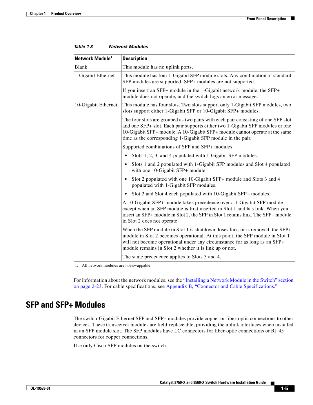
Table | Network Modules | |
|
| |
Network Module1 | Description | |
Blank |
| This module has no uplink ports. |
|
| |
This module has four | ||
|
| SFP modules are supported. SFP+ modules are not supported. |
|
| If you insert an SFP+ module in the |
|
| module does not operate, and the switch logs an error message. |
|
| |
This module has four slots. Two slots support only | ||
|
| slots support either |
|
| The four slots are grouped as two pairs with each pair consisting of one SFP slot |
|
| and one SFP+ slot. Each pair supports either two |
|
| |
|
| time as the corresponding |
|
| Supported combinations of SFP and SFP+ modules: |
|
| • Slots 1, 2, 3, and 4 populated with |
|
| • Slots 1 and 2 populated with |
|
| with one |
|
| • Slot 2 populated with one |
|
| populated with |
|
| • Slot 2 and Slot 4 each populated with |
|
| A |
|
| except when an SFP module is first inserted in Slot 1 and has link. When you |
|
| insert an SFP+ module in Slot 2, the SFP in Slot 1 retains link. The SFP+ module |
|
| in Slot 2 does not operate. |
|
| When the SFP module in Slot 1 is shutdown, loses link, or is removed, the SFP+ |
|
| module in Slot 2 becomes operational. At this point, the SFP module in Slot 1 |
|
| will not become operational under any circumstance for as long as an SFP+ |
|
| module remains in Slot 2 whether it is link up or not. |
|
| The same precedence applies to Slots 3 and 4. |
|
|
|
1. All network modules are
For information about the network modules, see the “Installing a Network Module in the Switch” section on page
SFP and SFP+ Modules
The
Use only Cisco SFP modules on the switch.
Catalyst
|
| ||
|
|
