Chapter 3 Power Supply and Fan Module Installation
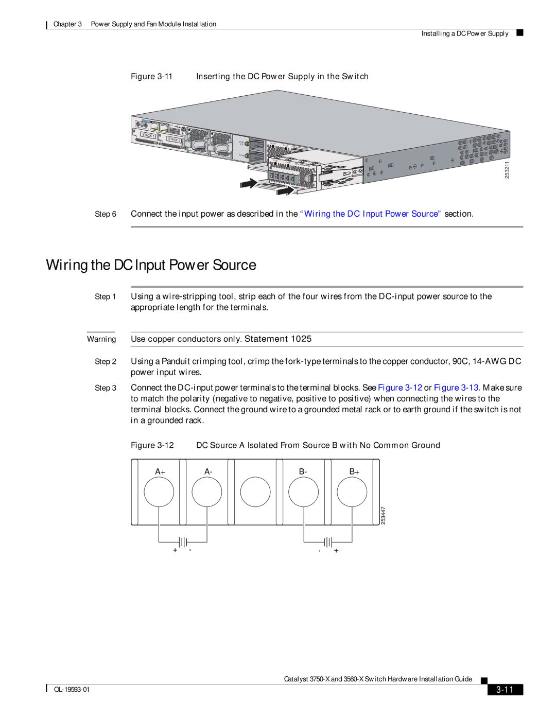
Figure 3-11 Inserting the DC Power Supply in the Switch
CONSOLE![]()
![]()
![]() AUX
AUX
STACK 1 | RESET |
|
|
|
|
|
|
| STACK | S- |
|
|
|
|
|
| 2 | AC |
|
|
|
| |
|
| PWR | OK |
|
|
| |
|
| XPS |
|
|
|
| |
|
|
|
| PS |
| C3 |
|
|
|
|
| OK |
|
| |
|
|
|
|
|
| ||
|
|
|
|
|
|
| 440WDC |
|
|
|
|
|
|
| |
|
|
|
| AC OK |
|
|
|
|
|
|
| PS | OK | C3 | |
|
|
|
|
|
|
| |
|
|
|
|
|
|
| 440WDC |
Installing a DC Power Supply
253211
Step 6 Connect the input power as described in the “Wiring the DC Input Power Source” section.
Wiring the DC Input Power Source
Step 1 Using a
Warning Use copper conductors only. Statement 1025
Step 2 Using a Panduit crimping tool, crimp the
Step 3 Connect the
Figure 3-12 DC Source A Isolated From Source B with No Common Ground
A+ | A- | B- | B+ |
253447
+ | - | - | + |
|
| Catalyst |
|
| |
|
|
| |||
|
|
|
| ||
|
|
|
| ||