Cisco Systems 3560-X, 3750-X Installing a DC Power Supply, Wiring the DC Input Power Source, page

Models: 3560-X 3750-X

1 114
Download 114 pages 50.92 Kb
Page 69
Image 69
Installing a DC Power Supply

Chapter 3 Power Supply and Fan Module Installation

Installing a DC Power Supply

Caution Do not leave the power-supply slot open for more than 90 seconds while the switch is operating.

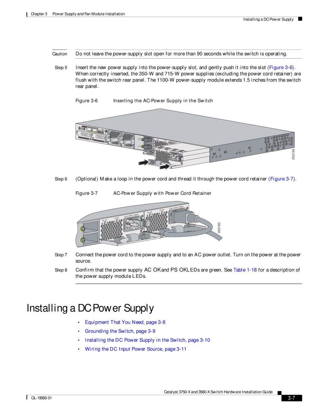
Step 5 Insert the new power supply into the power-supply slot, and gently push it into the slot (Figure 3-6). When correctly inserted, the 350-W and 715-W power supplies (excluding the power cord retainer) are flush with the switch rear panel. The 1100-W power-supply module extends 1.5 inches from the switch rear panel.

Figure 3-6 Inserting the AC-Power Supply in the Switch

CONSOLE•Equipment That You Need, page 3-8

•Installing the DC Power Supply in the Switch, page 3-10•Wiring the DC Input Power Source, page 3-11 AUX

STACK 1

RESET


STACK 2

S-PWR

XPS

S-PWR Manual background

AC OK


PS


C3

OK


KX-PWR-


715WAC

AC OK


PS

OK

C3


KX-PWR-


715WAC

253159

Step 6 (Optional) Make a loop in the power cord and thread it through the power cord retainer (Figure 3-7).

Figure 3-7 AC-Power Supply with Power Cord Retainer


-715WAC

C3KX

-PWR

PS OK


AC OK


-715WAC

C3KX

-PWR

PS OK


AC OK

253160

Step 7 Connect the power cord to the power supply and to an AC power outlet. Turn on the power at the power source.

Step 8 Confirm that the power supply AC OK and PS OK LEDs are green. See Table 1-18for a description of the power supply module LEDs.

Installing a DC Power Supply

Equipment That You Need, page 3-8

Grounding the Switch, page 3-9

Installing the DC Power Supply in the Switch, page 3-10

Wiring the DC Input Power Source, page 3-11

Catalyst 3750-X and 3560-X Switch Hardware Installation Guide


OL-19593-01

3-7


Page 69
Image 69
Cisco Systems 3560-X, 3750-X manual Installing a DC Power Supply, Equipment That You Need, page Grounding the Switch, page