Chapter 2 Switch Installation
Installing the Switch
StackPower Partitioning Examples
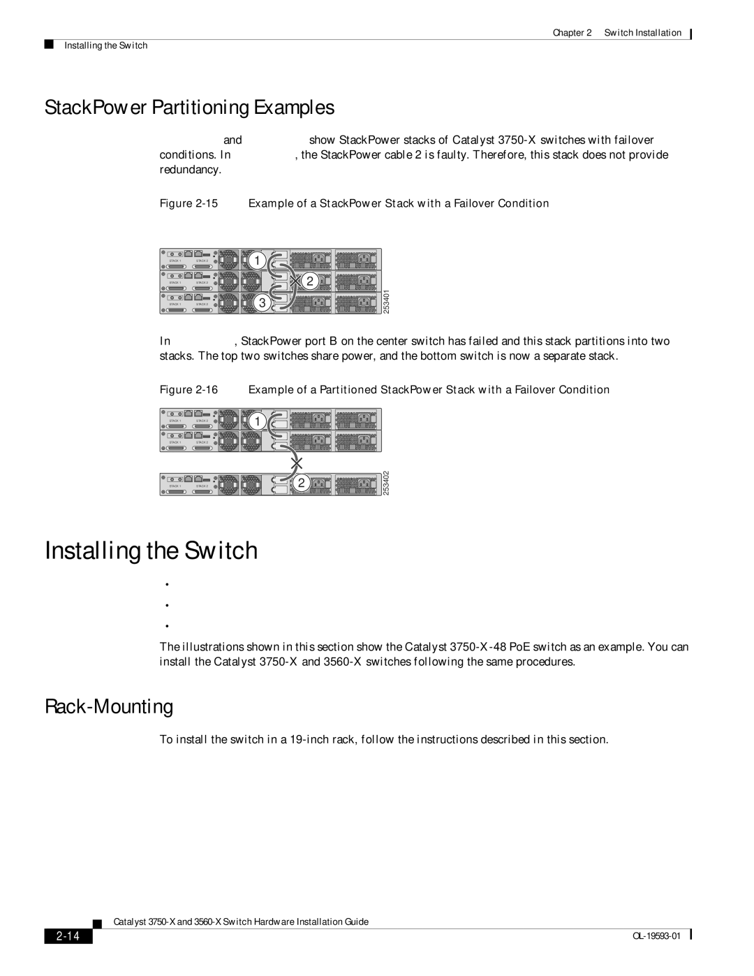
Figure 2-15 and Figure 2-16 show StackPower stacks of Catalyst 3750-X switches with failover conditions. In Figure 2-15, the StackPower cable 2 is faulty. Therefore, this stack does not provide redundancy.
Figure 2-15 Example of a StackPower Stack with a Failover Condition
STACK 1
STACK 1
STACK 1
STACK 2
STACK 2
STACK 2
1 |
| 2 |
3 | 253401 |
|
In Figure
Figure 2-16 Example of a Partitioned StackPower Stack with a Failover Condition
STACK 1 | STACK 2 | 1 |
|
STACK 1 | STACK 2 |
|
|
STACK 1 | STACK 2 | 2 | 253402 |
|
Installing the Switch
•
•Table- or
•After Installing the Switch, page
The illustrations shown in this section show the Catalyst
Rack-Mounting
To install the switch in a
Catalyst
|
| |
|