Chapter 2 Installing the Cisco SFS 7000P Switch
Configuring Basic Connectivity
Powering Up the Chassis
When you power up the chassis, use only the power cable provided with your InfiniBand system.
To power up the chassis, follow these steps:
Step 1 Remove the power cords from the shipping package.
Two power cords are available:
Step 2 Inspect the power cord and determine if it provides the proper plug and is appropriately certified for use with your electrical system. Discard the cord if it is inappropriate for your national electrical system and obtain the proper cord, as required by your national electrical codes or ordinances.
Grounding is supplied by the ground prong on the
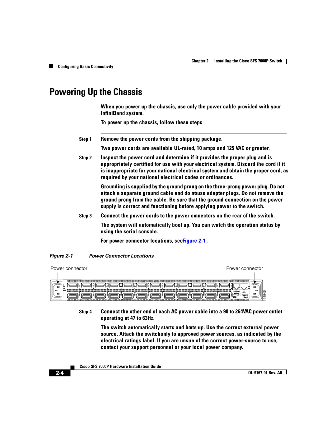
Step 3 Connect the power cords to the power connectors on the rear of the switch.
The system will automatically boot up. You can watch the operation status by using the serial console.
For power connector locations, see Figure
Figure 2-1 Power Connector Locations
Power connector | Power connector |
144945
Step 4 Connect the other end of each AC power cable into a 90 to 264VAC power outlet operating at 47 to 63Hz.
The switch automatically starts and boots up. Use the correct external power source. Attach the switch only to approved power sources, as indicated by the electrical ratings label. If you are unsure of the correct
| Cisco SFS 7000P Hardware Installation Guide |
