Chapter 3 Maintaining the Server
Preparing for Component Installation
Removing and Replacing the Server Front Cover (Small Form Factor Only)
Note It is not necessary to remove the front cover unless instructed to do so in a replacement procedure.
To remove or replace the front cover of the SFF version of the server (PID
Step 1 Remove a front cover:
a.Remove the server top cover, as described in Removing and Replacing the Server Top Cover, page
b.Use a Number 2
c.Lift the front cover straight up off of the chassis.
Step 2 Replace a front cover:
a.Set the front cover back in place, aligning the screw holes in the cover with those in the chassis.
b.Replace the 10 securing screws.
c.Replace the top cover as described in Removing and Replacing the Server Top Cover, page
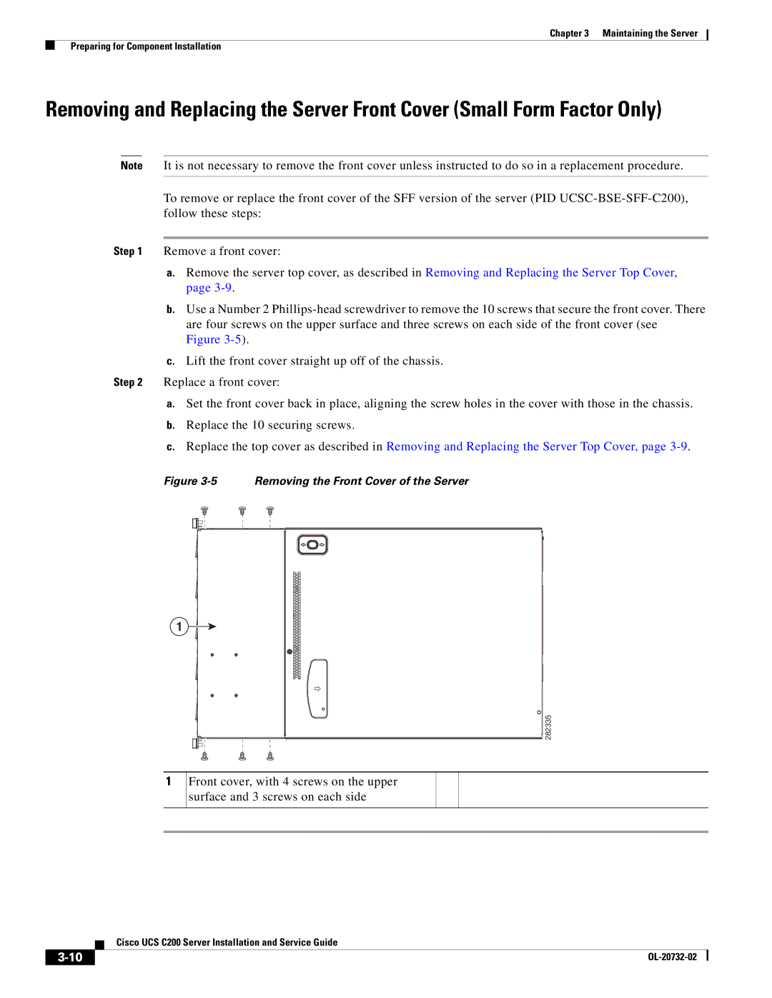
Figure 3-5 Removing the Front Cover of the Server
1
282335
1
Front cover, with 4 screws on the upper surface and 3 screws on each side
| Cisco UCS C200 Server Installation and Service Guide |
|