Chapter 3 Maintaining the Server
Installing or Replacing Components
Note The rear edge of the front cover should go under the black plastic cable cover.
f.Replace the top cover as described in the “Removing and Replacing the Server Top Cover” section on page
g.Replace the server in the rack, replace power cords and any other cables, and then power on the server by pressing the Power button.
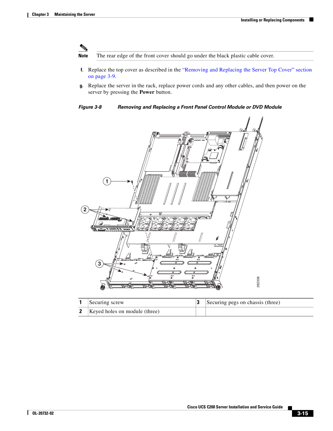
Figure 3-8 Removing and Replacing a Front Panel Control Module or DVD Module
1
2 ![]()
![]()
![]()
![]()
![]()
![]()
![]()
3 ![]()
![]()
![]()
![]()
282338
1
2
Securing screw | 3 Securing pegs on chassis (three) |
Keyed holes on module (three)
|
| Cisco UCS C200 Server Installation and Service Guide |
|
| |
|
|
| |||
|
|
|
| ||
|
|
|
| ||