Chapter 2 Installing the Server
Installing the Server Into a Rack
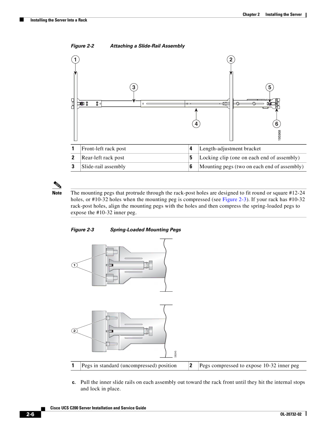
Figure 2-2 Attaching a Slide-Rail Assembly
1 | 2 |
| 3 |
| 4 |
5
6
195968
1 | 4 | ||
|
|
|
|
2 | 5 | Locking clip (one on each end of assembly) | |
|
|
|
|
3 | 6 | Mounting pegs (two on each end of assembly) | |
|
|
|
|
Note The mounting pegs that protrude through the
Figure 2-3 Spring-Loaded Mounting Pegs
1
2
330245
1
Pegs in standard (uncompressed) position
2
Pegs compressed to expose
c.Pull the inner slide rails on each assembly out toward the rack front until they hit the internal stops and lock in place.
Cisco UCS C200 Server Installation and Service Guide
|
| |
|