Chapter 3 Maintaining the Server
Installing or Replacing Components
Note Be careful to align the
b.Place the new BBU over the BBU bracket on the fan tray and align the three
c.Replace the three securing screws that hold the BBU to the BBU bracket.
Step 3 If this is a
Connect the cable from the BBU to the socket on the adapter.
Note Be careful to align the
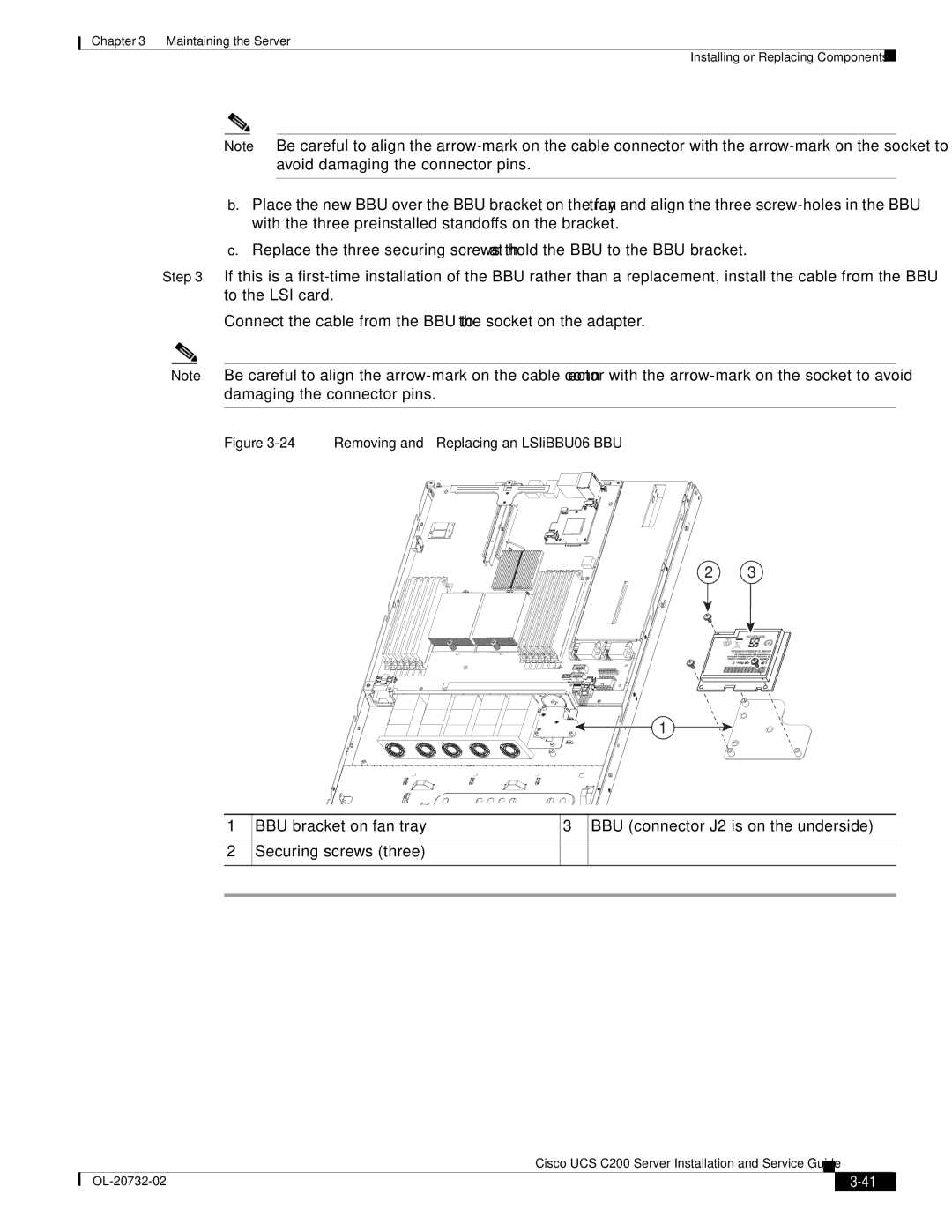
Figure 3-24 Removing and Replacing an LSIiBBU06 BBU
2 3
1
1
2
BBU bracket on fan tray | 3 BBU (connector J2 is on the underside) |
Securing screws (three) |
|
|
| Cisco UCS C200 Server Installation and Service Guide |
|
| |
|
|
| |||
|
|
|
| ||
|
|
|
| ||