Chapter 1 Overview
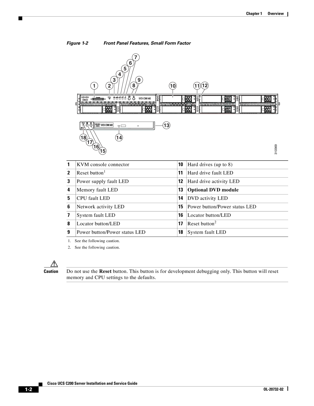
Figure 1-2 Front Panel Features, Small Form Factor
|
| 7 |
|
|
|
| 6 |
|
|
|
| 5 |
|
|
| 3 | 4 | 9 |
|
| 8 | 11 12 | ||
1 | 2 | 10 | ||
|
| 13 |
| |
|
|
|
| |
18 |
| 14 |
|
|
17 |
|
|
|
|
16 | 15 |
|
| 310369 |
|
|
| ||
|
|
|
|
1 | KVM console connector | 10 | Hard drives (up to 8) |
|
|
|
|
2 | Reset button1 | 11 | Hard drive fault LED |
3 | Power supply fault LED | 12 | Hard drive activity LED |
|
|
|
|
4 | Memory fault LED | 13 | Optional DVD module |
|
|
|
|
5 | CPU fault LED | 14 | DVD activity LED |
|
|
|
|
6 | Network activity LED | 15 | Power button/Power status LED |
|
|
|
|
7 | System fault LED | 16 | Locator button/LED |
|
|
|
|
8 | Locator button/LED | 17 | Reset button2 |
9 | Power button/Power status LED | 18 | System fault LED |
|
|
|
|
1.See the following caution.
2.See the following caution.
Caution Do not use the Reset button. This button is for development debugging only. This button will reset memory and CPU settings to the defaults.
Cisco UCS C200 Server Installation and Service Guide
|
| |
|
