Connecting the Cisco SLM2008 Switch | 3 |
| |
Connecting the Cisco SLM2008 Switch to the Network |
|
|
|
|
|
STEP 3 Insert a screw into each hole and leave 3 mm of its head exposed.
STEP 4 The
Wall
mount
slots
![]()
![]()
![]()
![]()
![]() 194450
194450
STEP 5 Maneuver the switch to insert the screws into the two slots.
Connecting the Cisco SLM2008 Switch to the Network
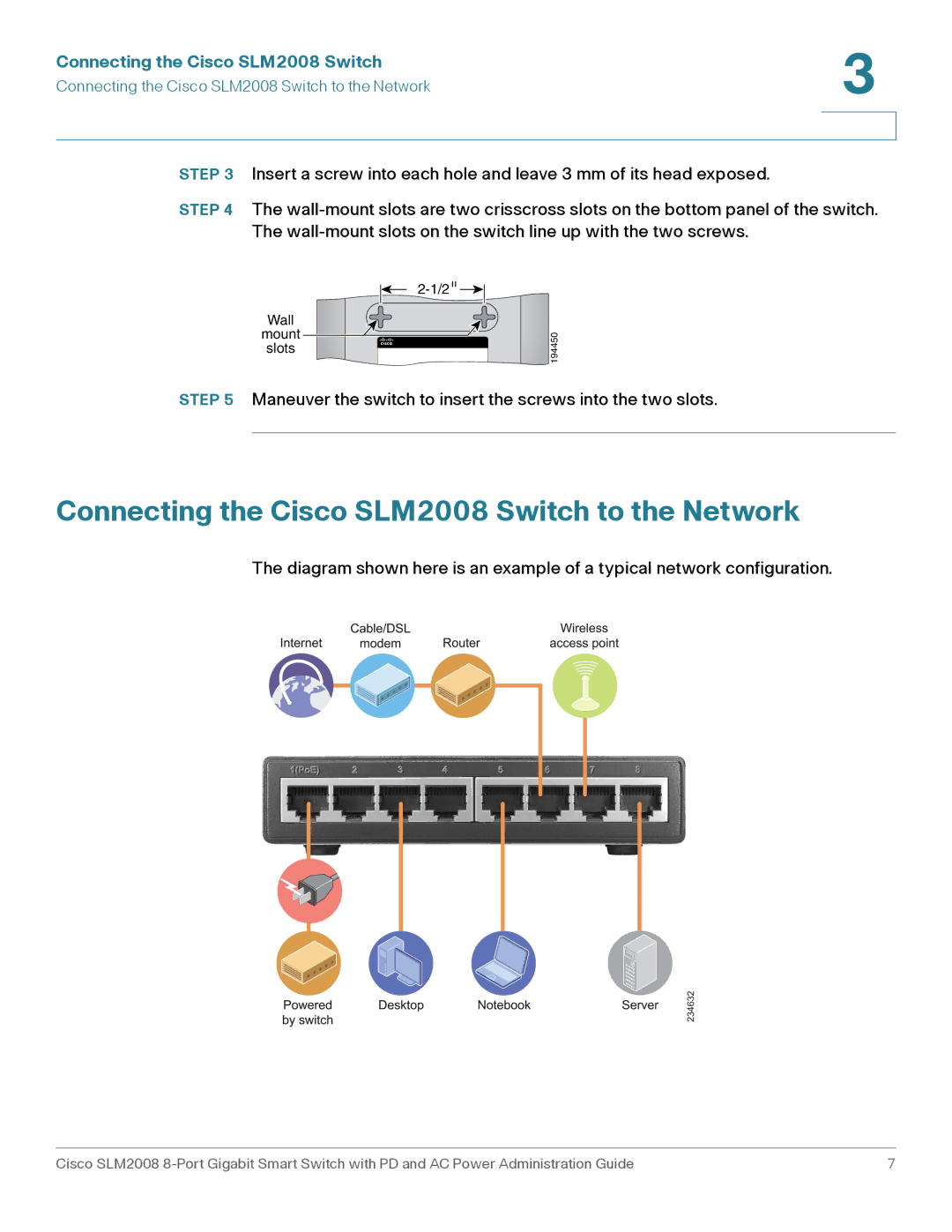
The diagram shown here is an example of a typical network configuration.
Cisco SLM2008 | 7 |
